Grid fin device

A grid rudder and unlocking device technology, applied to projectiles, self-propelled bombs, offensive equipment, etc., can solve the problem that there is no improvement plan for the pin shaft limit scheme of the pin puller, and achieve easy welding quality and high reliability , the effect of reducing production costs

Active Publication Date: 2019-09-20
SHANGHAI AEROSPACE SYST ENG INST
View PDF6 Cites 4 Cited by
  • Summary
  • Abstract
  • Description
  • Claims
  • Application Information

AI Technical Summary

Problems solved by technology

There is no improvement plan for this defect in the pin limit plan of the pin puller

Method used


Image

  • Grid fin device
  • Grid fin device
  • Grid fin device

Examples


Embodiment 1

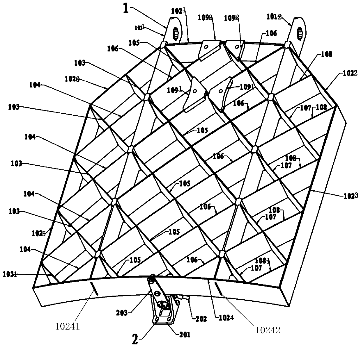
[0049] The invention provides a grid rudder device, such as figure 1 As shown, it includes a rudder surface structure 1 and a locking and unlocking device 2 .

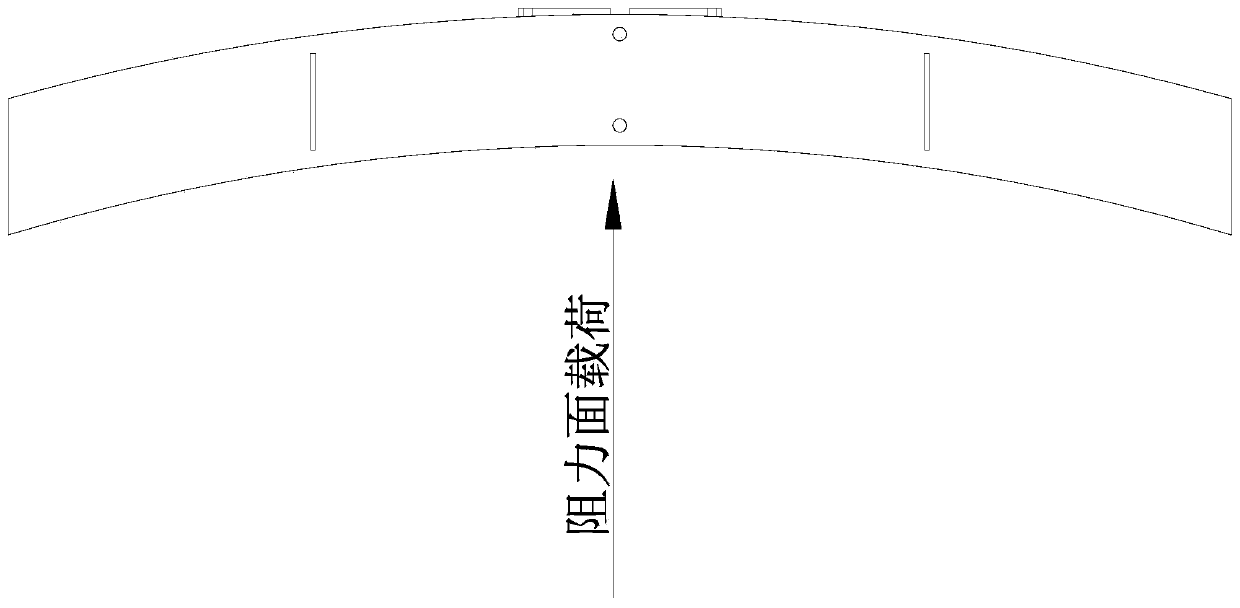
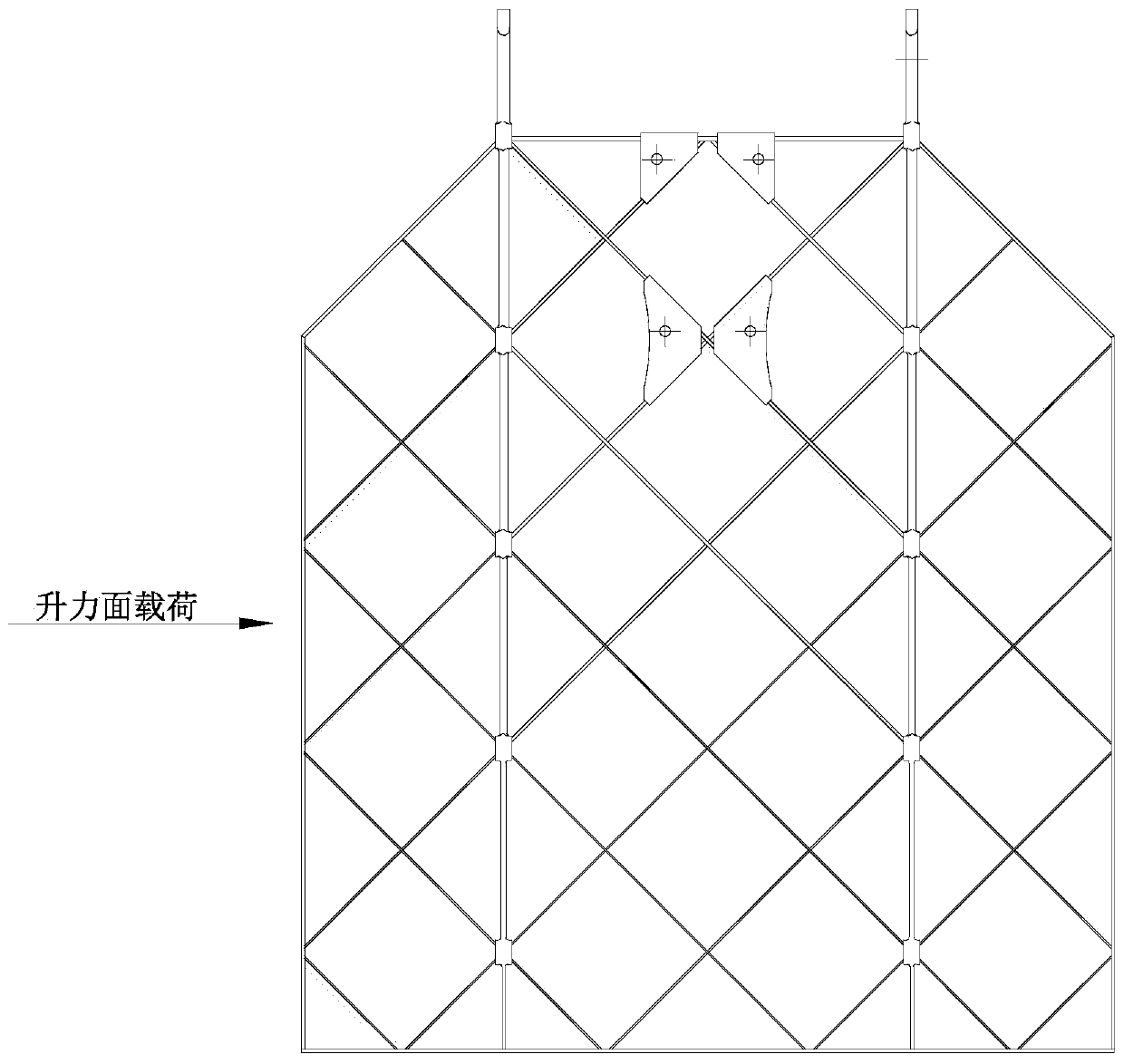
[0050] The rudder surface structure 1 comprises: a first rudder root 1011, a second rudder root 1012, a rudder frame 102, a first blade 103, a second blade 104, a third blade 105, a fourth blade 106, a fifth blade 107, a Six blades 108, adapter plate 109. The joints of the rudder root 101, rudder frame 102, blades 103-108, and adapter plate 109 are all designed with ±45° U-shaped semi-through grooves. After being inserted into each other and positioned, the overall welding is formed, such as figure 1 As shown; the load carried by the rudder surface structure is two major parts of the lift surface and the resistance surface load, such as figure 2 , image 3 , Figure 4 shown;

[0051] The rudder root 101 has a gradual cross-sectional thickness structure, which is thinner near the locking device side and thicker ne...


PUM


Abstract

The invention discloses a grid fin surface device. The grid fin surface device comprises a fin surface structure and a locking and unlocking device, the fin surface structure is connected with the locking and unlocking device, wherein the fin surface structure comprises a first fin root, a second fin root, a fin frame and several blades, the first fin root and the second fin root are connected with the fin frame correspondingly, moreover, the first fin root and the second fin root divide the fin frame into a first area, a second area and a third area, and the several blades are arranged at the first area, the second area and the third area. According to the grid fin surface device, a structure initial splicing bearing and welding auxiliary positioning scheme is adopted, a scheme of inserting a pin puller pin shaft into a spherical hinge hole is adopted, so that the grid fin surface device has the advantages of being stable and reliable in bearing performance and capable of achieving deformation compensation capability.

Description

technical field [0001] The invention belongs to the technical field of the first sub-stage of launch vehicles, and in particular relates to a grid rudder device. Background technique [0002] At present, grid rudder surfaces formed by welding and casting have been widely used in the attitude control of missiles, spaceships, and the first stage of launch vehicles during flight or return. However, the casting scheme is integrally formed, which has high reliability but relatively high production costs high. In the face of high-quality, low-cost competition in the aerospace launch market, the cost of tailor-welded sheet metal solutions is low, but limited by factors such as welding process stability and undetectability, the welding quality reliability assessment of tailor-welded solutions depends on the same batch of welding The circumstantial evidence of small samples cannot be directly evaluated, and there are certain risks in the application of models. [0003] In addition,...

Claims


Application Information

Patent Timeline
Patent Type & Authority Applications(China)
IPC IPC(8): F42B10/14F42B15/00
CPCF42B10/143F42B15/00
Inventor 秦震李新宽吴春雷陈雪巍宋林郁古艳峰陈鸣亮王业伟
Owner SHANGHAI AEROSPACE SYST ENG INST
Why Eureka
Try Eureka