
Working condition self-adaptive driving system of loading machine

A transmission system, self-adaptive technology, applied in transmission, fluid transmission, transmission parts, etc., can solve the problems of inability to achieve power ratio, insufficient input power, excess power occupied by the system, etc., to achieve the ability of manual intervention. Effect

Active Publication Date: 2019-09-20
HUAIAN COLLEGE OF INFORMATION TECH
View PDF6 Cites 1 Cited by
  • Summary
  • Abstract
  • Description
  • Claims
  • Application Information

AI Technical Summary

Problems solved by technology

[0003] Many systems of the loader need power to operate, such as the wheel system, brake system, hydraulic system, oil circulation system, etc., all of which obtain power from the output shaft of the diesel engine through the transmission system. The power system of the original loader is rigid to the load. Connected, how much power is transmitted to the load in the past, is set according to the complex electromechanical combined system of the original power system, often this system takes up excess power, and the input power of other systems is insufficient to achieve an adaptive power ratio

Method used


Image

  • Working condition self-adaptive driving system of loading machine
  • Working condition self-adaptive driving system of loading machine
  • Working condition self-adaptive driving system of loading machine

Examples


Embodiment Construction

[0027] The following will clearly and completely describe the technical solutions in the embodiments of the present invention with reference to the accompanying drawings in the embodiments of the present invention. Obviously, the described embodiments are only some, not all, embodiments of the present invention. Based on the embodiments of the present invention, all other embodiments obtained by persons of ordinary skill in the art without making creative efforts belong to the protection scope of the present invention.

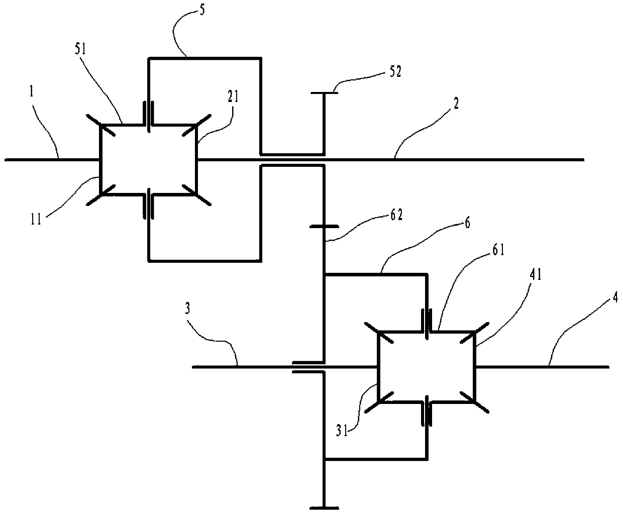
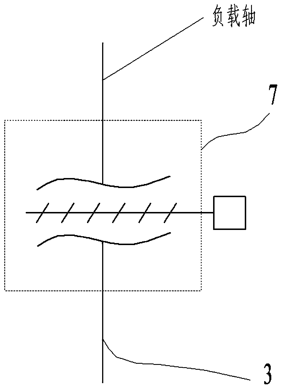
[0028] Such as figure 1 , Figure 6 As shown, a working condition adaptive transmission system includes a basic unit 100 and a variable force hydraulic coupling 7, the basic unit 100 is connected to the input shaft 1, and the basic unit 100 distributes the power of the input shaft 1 to several loads through several gear sets shaft, the power distribution ratio is linearly related to the power demand ratio of the load shaft, and the basic unit 100 is connected...


PUM


Abstract

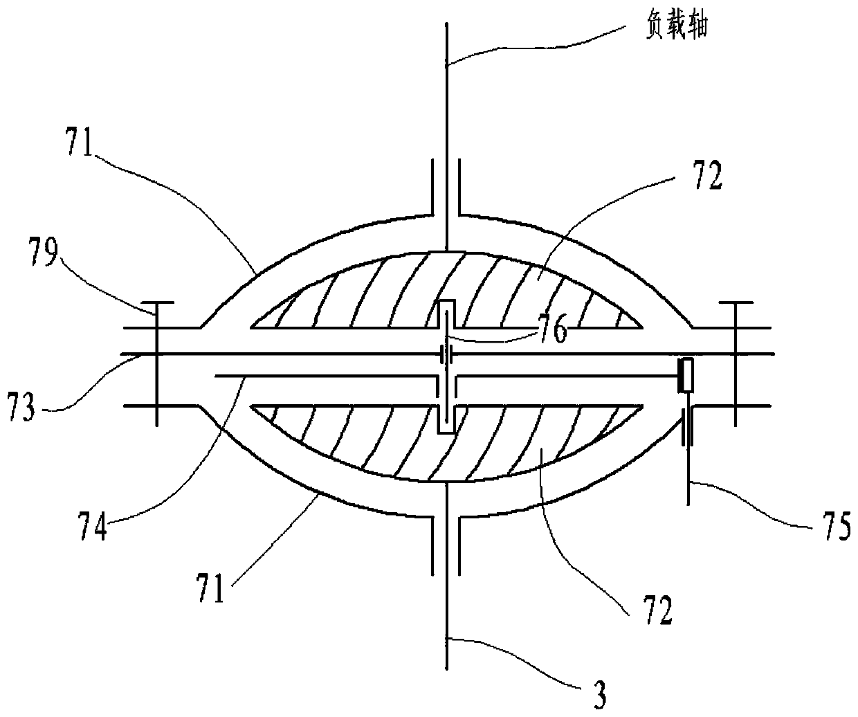
The invention discloses a working condition self-adaptive driving system of a loading machine. The working condition self-adaptive driving system comprises an elementary unit and a variable force hydraulic coupler. The elementary unit is connected with an input shaft. The elementary unit is connected with a plurality of load shafts through the variable force hydraulic coupler. In the elementary unit, a first gear, a second gear and a first force distribution wheel constitute a planet gear driving system, a second force distribution wheel, a third gear and a fourth gear constitute a planet gear system, the rotating speeds of three output shafts can be automatically adjusted according to rotating resistance of the three output shafts, and self-adaptive working condition regulation is realized. A first baffle plate is clamped by two shells of the variable force hydraulic coupler clamps and then fixed through fasteners. The shells are provided with two hydraulic coupling wheels which are spaced through the first baffle plate. A second baffle plate on one side of the first baffle plate can rotate to change the overlapping area of second blocking holes and first blocking holes so as to change the shaft connecting power of the hydraulic coupler.

Description

technical field [0001] The invention relates to the field of loaders, in particular to a working condition adaptive transmission system of the loader. Background technique [0002] Loader is a kind of engineering auxiliary machinery widely used in construction, which has functions such as bulldozing, lifting, loading and unloading. [0003] Many systems of the loader need power to operate, such as the wheel system, brake system, hydraulic system, oil circulation system, etc., all of which obtain power from the output shaft of the diesel engine through the transmission system. The power system of the original loader is rigid to the load. Connected, how much power is transmitted to the load in the past, is set according to the complex electromechanical combined system of the original power system, often this system takes up excess power, and the input power of other systems is insufficient to achieve an adaptive power ratio . Contents of the invention [0004] The object o...

Claims


Application Information

Patent Timeline
Patent Type & Authority Applications(China)
IPC IPC(8): F16H47/12F16H57/08
CPCF16H47/12F16H57/08
Inventor 刘朋张秋霞李园园赵连星豆琼森李文龙夏永芳孔勇杰
Owner HUAIAN COLLEGE OF INFORMATION TECH
Learn More