Tile paving and pasting device method
A ceramic tile and paving technology, which is applied to floors, elastic floors, insulating layers, etc., can solve the problems of inconvenient replacement of tiles, cracked corners of tiles, and large stress on the mortar, so as to facilitate the replacement of tiles, save costs, and reduce costs. The effect of beautiful sewing work convenience
- Summary
- Abstract
- Description
- Claims
- Application Information
AI Technical Summary
Problems solved by technology
Method used
Image

Examples
Embodiment 1
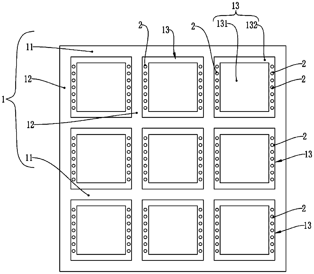
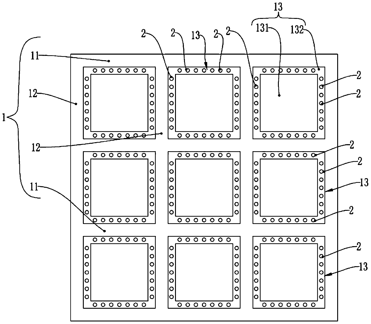
[0038] The tile laying device of the present embodiment, as figure 1 , figure 2 As shown, a support frame 1 is included, and the support frame 1 is composed of a plurality of mutually perpendicular transverse support segments 11 and longitudinal support segments 12 to form a grid structure, and each network formed by the transverse support segments 11 and the longitudinal support segments 12 Grid is each ceramic tile installation unit 13, is characterized in that:
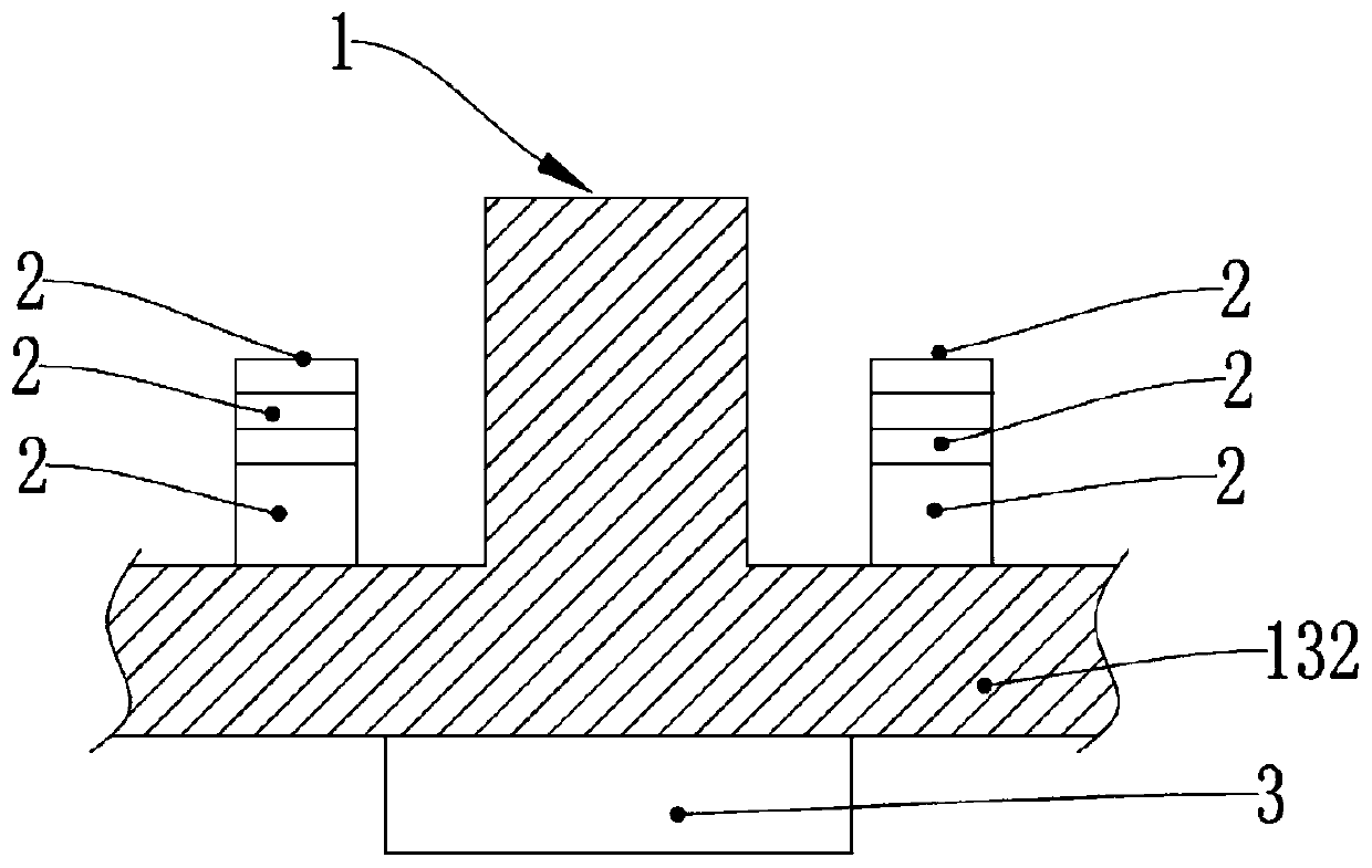
[0039] The tile installation unit 13 includes an installation cavity 131 and an installation platform body 132, the installation platform body 132 is arranged around the grid surrounded by the horizontal support section 11 and the longitudinal support section 12, and the top surface of the installation platform body 132 is low. On the top surfaces of the transverse support section 11 and the longitudinal support section 12, the middle part of the installation table body 132 is hollowed out to form the installatio...
Embodiment 2
[0056] In the tile laying device of the present embodiment, as Figure 5 to Figure 7 As shown, the height adjustment structure of the support column 2 is a bayonet structure, and the side surface of the support column 2 is uniformly distributed with external tooth-shaped protrusions 21 in parallel, and the installation table body 132 is provided with corresponding installation holes. The hole is provided with an inner tooth-shaped protrusion 133;
[0057] The external tooth-shaped protrusion 21 is an arc-shaped external tooth 211 that is arranged opposite to each other in the horizontal direction and is less than 1 / 4 of the arc length of the outer arc. 1 / 4 arc-shaped internal teeth 134 with a length of 1 / 4 internal arc, the tooth shapes of the external tooth-shaped protrusion 21 and the internal tooth-shaped protrusion 133 cooperate with each other. Other technical characteristics are identical with embodiment 1.
[0058] When inserting the support column 2 into the installa...
Embodiment 3
[0060] In the tile laying device of the present embodiment, as Figure 8 to Figure 11 As shown, the top of the support frame 1 is also provided with an auxiliary groove 14, and the auxiliary groove 14 runs through all the transverse support sections 11 and the longitudinal support sections 12 to form a grid-like groove structure. Other technical features are the same as in Embodiment 1, or other technical features are the same as in Embodiment 2.
[0061] The auxiliary groove 14 can be used for filling the joint agent, and can also be used for accommodating ground pipelines such as electric wires and water pipes. Now the house decoration will arrange the pipelines on the ground, and then pave the tiles with cement. Once a pipeline failure occurs, it is difficult to check the ground pipelines, and the tiles need to be pried open or smashed, which is extremely troublesome. The tile laying device is provided with an auxiliary groove 14, which can store the ground pipeline in the...
PUM
 Abstract
Description
Claims
Application Information
 - R&D
- Intellectual Property
- Life Sciences
- Materials
- Tech Scout
- Unparalleled Data Quality
- Higher Quality Content
- 60% Fewer Hallucinations
Browse by: Latest US Patents, China's latest patents, Technical Efficacy Thesaurus, Application Domain, Technology Topic, Popular Technical Reports.
© 2025 PatSnap. All rights reserved.Legal|Privacy policy|Modern Slavery Act Transparency Statement|Sitemap|About US| Contact US: help@patsnap.com