Vertical face turning device for cylindrical workpiece

A cylindrical workpiece and flipping technology, which is applied in the field of automatic flipping devices, can solve the problems of low cost and achieve the effects of low cost, simple and reliable flipping process, and easy industrialization

Pending Publication Date: 2019-09-20
新昌浙江工业大学科学技术研究院
View PDF1 Cites 2 Cited by
  • Summary
  • Abstract
  • Description
  • Claims
  • Application Information

AI Technical Summary

Problems solved by technology

The up and down turning device of the cylindrical workpiece of the present application has an exquisite and simple structure design, and can realize the turning of the cylindrical object only relying on structural features and gravity, without manual or complicated manipulator operation, low cost, high work efficiency, and convenient for industrialization; It has strong adaptability, the components to be turned over are not limited by the material, and can complete the up and down turning operation of rollers with relatively small height and diameter, which effectively solves the problem that it is difficult to adapt to small height cylindrical workpieces by grasping and turning in the past. The turning process is simple and reliable, which can significantly improve the efficiency of turning up and down cylindrical workpieces, effectively saving time, and its turning speed can adapt to the processing or testing of cylindrical rollers in the form of high-efficiency assembly lines

Method used


Image

  • Vertical face turning device for cylindrical workpiece
  • Vertical face turning device for cylindrical workpiece
  • Vertical face turning device for cylindrical workpiece

Examples


Embodiment 1

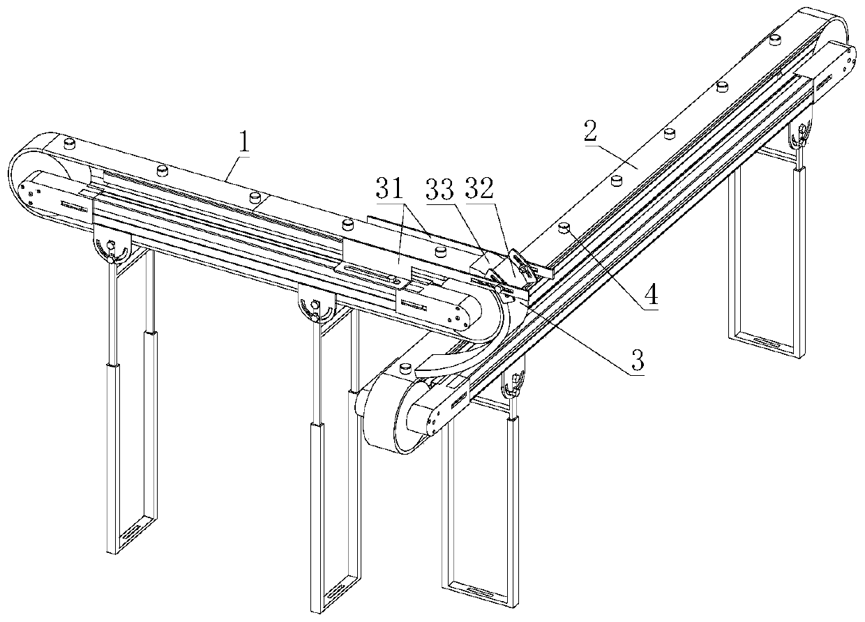
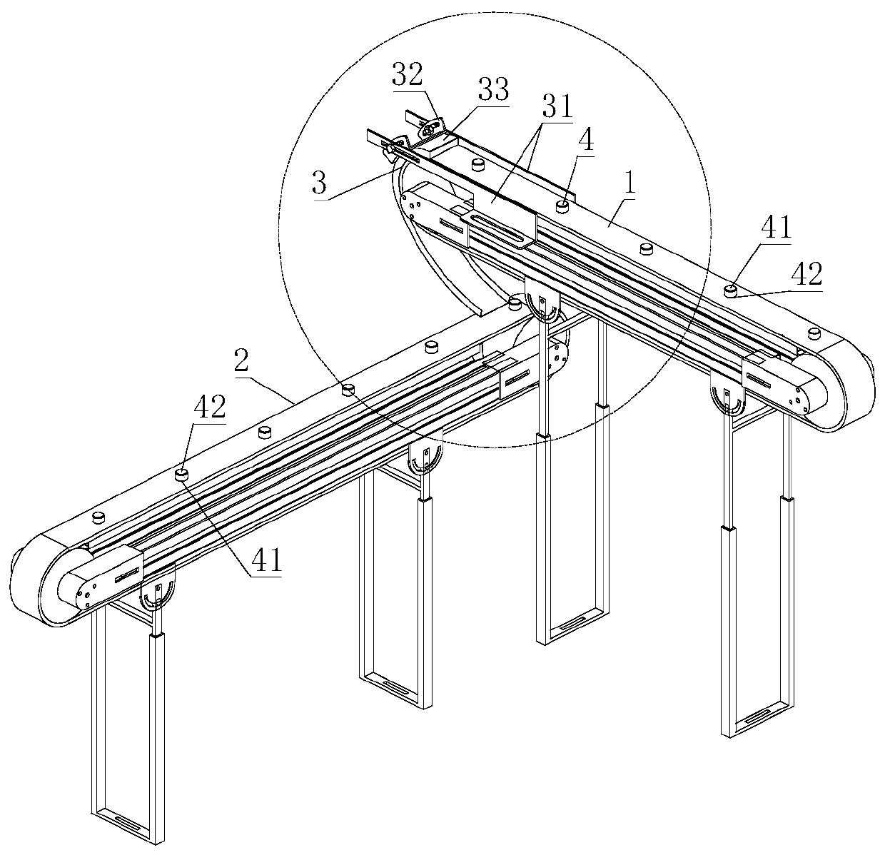
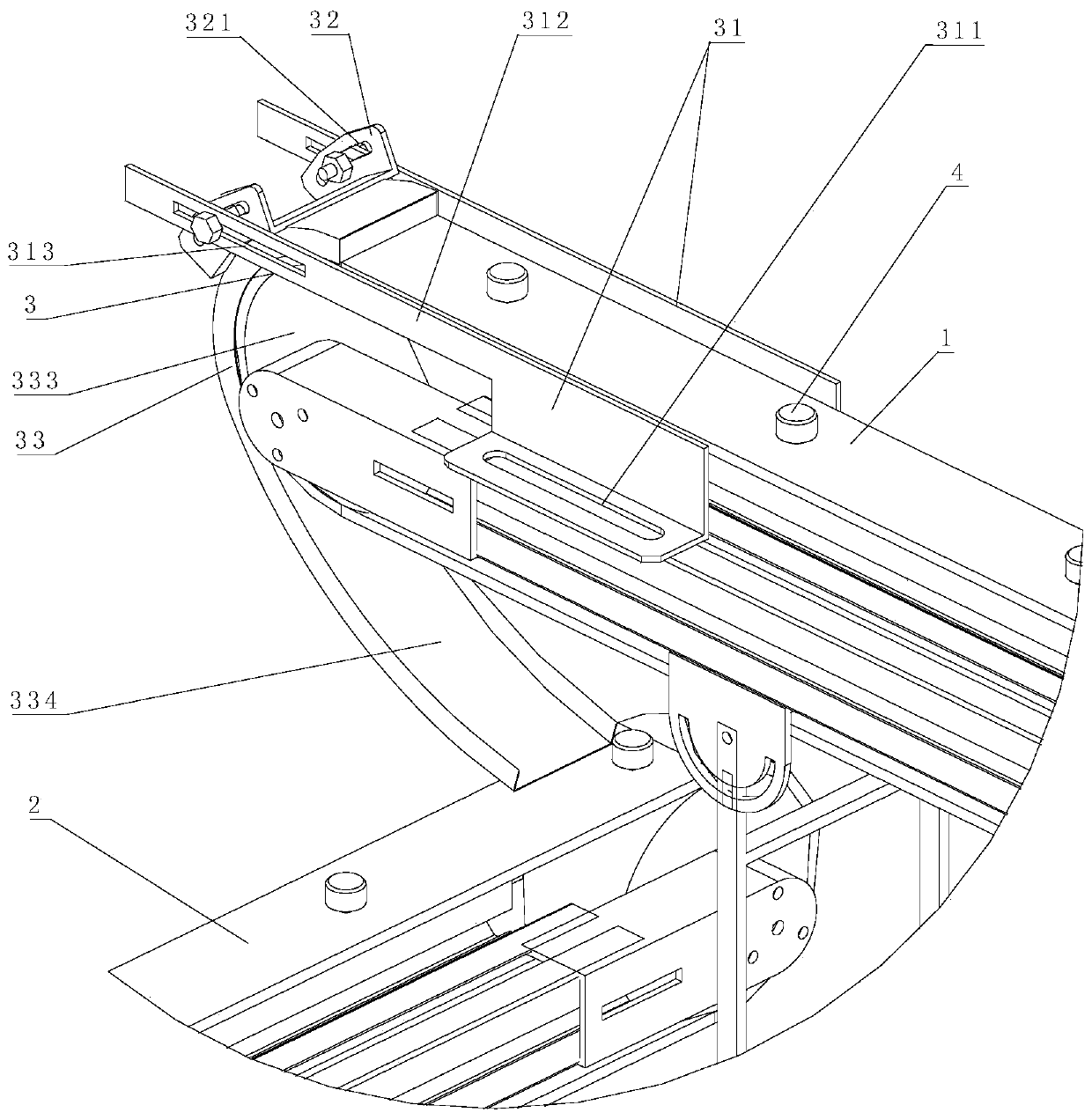
[0030] see Figure 1-5 , the up and down turning device of the cylindrical workpiece of the present invention comprises an upper conveyor belt 1 and a lower conveyor belt 2; the feeding end of the upper conveyor belt 1 is located above the feeding end of the lower conveyor belt 2; The end is connected with the feeding end of the lower conveyor belt 2 through the turning device 3; the turning device 3 includes an arc-shaped turning slide 33, and the entrance of the arc-shaped turning slide 33 is connected with the feeding end of the upper conveyor belt 1, The outlet of the arc-shaped turning slide 33 is connected with the feeding end of the lower conveyor belt 2, and the radius of curvature at the inlet of the arc-shaped turning slide 33 is consistent with the radius of curvature of the feeding end of the upper conveyor belt 1.

[0031] see Figure 7, the arc-shaped turning slide 33 is divided into upper and lower sections; wherein, the radius of curvature R1 of the upper sect...

Embodiment 2

[0038] The difference between this embodiment and Embodiment 1 is that the radius of curvature of the arc-shaped turning slide 33 gradually increases from the entrance to the exit. When adjusting the position of the arc-shaped turning slide 33 relative to the conveyor belt 1, the distance between the conveyor belt 1 and the slide surface of the upper section 333 does not change much, preventing the cylindrical workpiece 4 from overturning when turning over.

Embodiment 3

[0040] see Image 6 The difference between this embodiment and the above-mentioned embodiments is that the arc-shaped turning slide 33 is a long tube with a rectangular cross section, and the upper end of the arc-shaped turning slide 33 is provided with an opening groove 331 facing the upper conveyor belt 1, The end cross section of the opening groove 331 is a cylindrical workpiece butt surface 332, the cylindrical workpiece butt surface 332 is located below the cut surface of the end of the upper conveyor belt 1, and the outer edge of the cylindrical workpiece butt surface 332 is left between the upper conveyor belt 1 There is a gap, and the height of the cross section of the arc-shaped turning slide 33 is greater than the height of the cylindrical workpiece 4 . The bottom of the arc-shaped turning slide 33 is closed, and the cylindrical workpiece docking surface 332 is docked with the lower semicircle of the upper conveyor belt 1, which can effectively protect the cylindrica...


PUM


Abstract

The invention relates to a vertical face turning device for a cylindrical workpiece. The vertical face turning device for the cylindrical workpiece comprises an upper conveyer belt, a lower conveyer belt and a face turning device arranged between the discharging end of the upper conveyer belt and the feeding end of the lower conveyer belt; the upper conveyer belt and the lower conveyer belt are vertically arranged in a staggered mode, the conveying directions of the upper conveyer belt and the lower conveyer belt are perpendicular to each other, and the discharging end of the upper conveyer belt and the feeding end of the lower conveyer belt correspond to each other and are connected end to end through the face turning device; and the face turning device comprises arc-shaped face turning slide position adjusting brackets arranged on the two sides of the discharging end of the upper conveyer belt, an arc-shaped face turning slide inclination angle adjusting bracket arranged between the two arc-shaped face turning slide position adjusting brackets and an arc-shaped face turning slide fixedly connected with the arc-shaped face turning slide position adjusting brackets. According to the vertical face turning device for the cylindrical workpiece, the structural design is exquisite and simple, manual or complex manipulator operation is not needed, the cost is low, the working efficiency is high, and industrialization is convenient to achieve; and the adaptability is high, an element to be subjected to face turning is not limited by the material, vertical face turning operation of a roller with the very small height-diameter ratio can be completed, and the face turning efficiency is high.

Description

technical field [0001] The application relates to the technical field of automatic flipping devices, in particular to an up and down flipping device for cylindrical workpieces. Background technique [0002] Flat cylindrical workpieces often need to be processed and inspected on both sides, but processing or inspection equipment can only process or inspect one surface at a time. Therefore, when processing or inspecting the upper and lower surfaces of cylindrical workpieces, it is necessary to The upper and lower sides of the type workpiece are turned over. At present, manual reversal or manipulator reversal is mainly used. Manual reversal has obvious disadvantages, such as low reversal efficiency, inaccurate positioning of manual transposition after reversal, and fatigue of workers who do the same job for a long time. It is beneficial to the automation of the production process, etc.; the reverse of the manipulator uses the chuck of the manipulator to clamp the side of the c...

Claims


Application Information

Patent Timeline
IPC IPC(8): B65G47/248
CPCB65G47/248B65G2201/02
Inventor 张冬峰周见行吕迅袁巨龙王志毫张万辉
Owner 新昌浙江工业大学科学技术研究院
Why Eureka
Try Eureka