Two-horizontal two-vertical blade rotatable four-wheel dynamic wing UAV
A technology of drones and blades, which is applied to unmanned aircraft, fuselages, motor vehicles, etc., can solve the problems of high energy consumption, low aerodynamic efficiency, and large forward resistance, and achieve good maneuverability, simple structure, The effect of drag reduction
- Summary
- Abstract
- Description
- Claims
- Application Information
AI Technical Summary
Problems solved by technology
Method used
Image

Examples
Embodiment 1
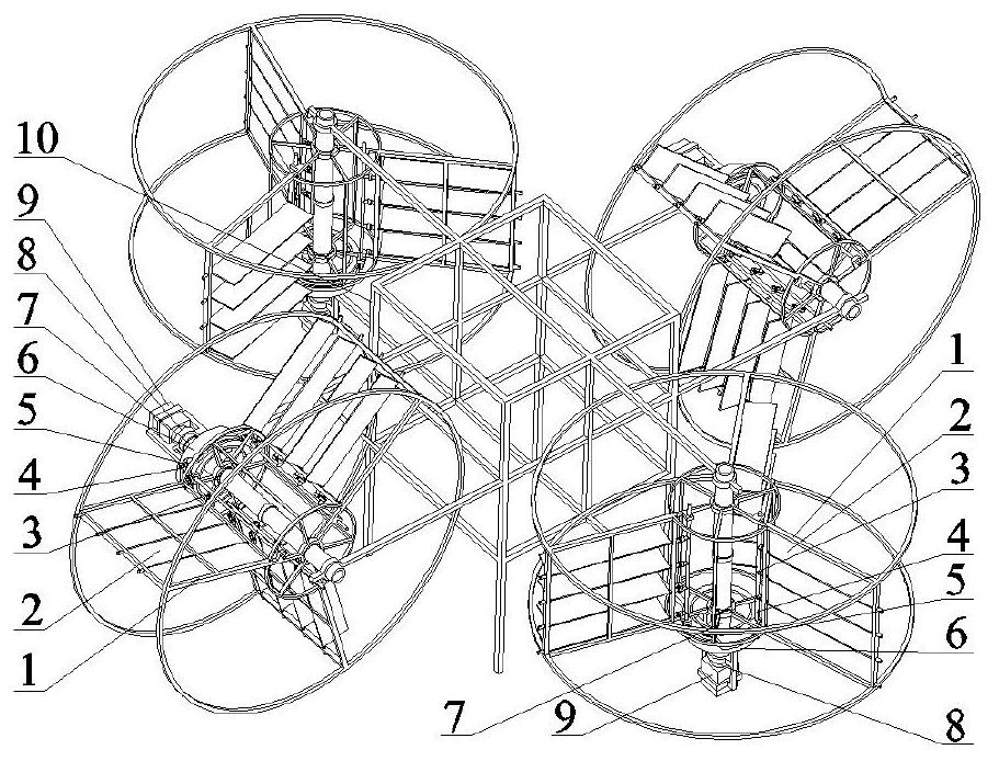
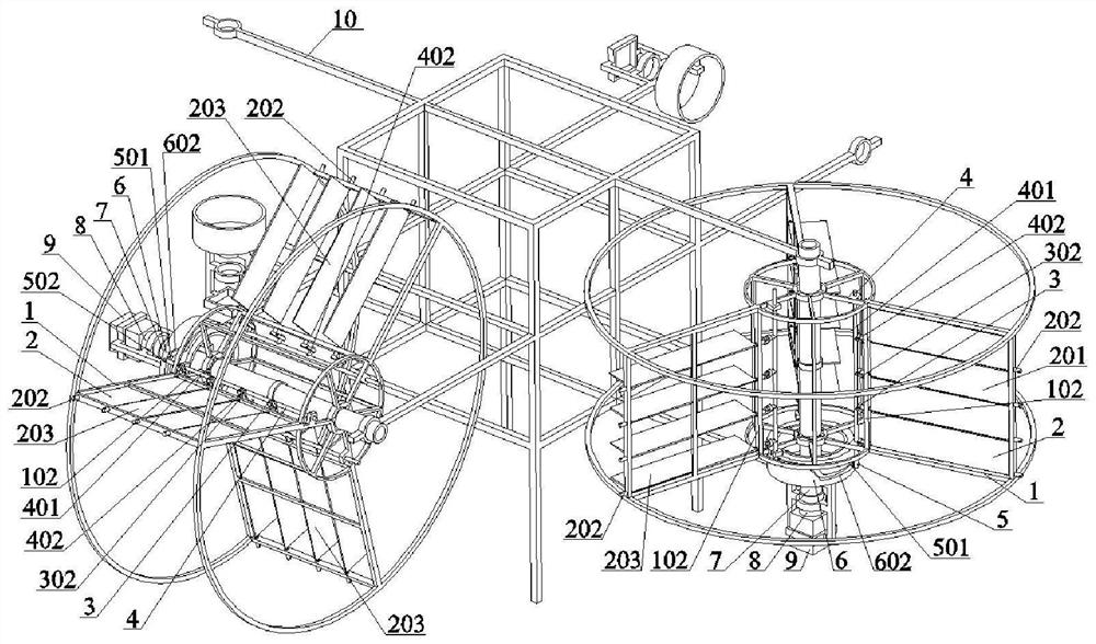
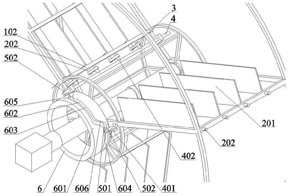
[0032] combine figure 1 , figure 2 , image 3 , Figure 4 , Figure 5 , Figure 6 , Figure 7 , Figure 8 , Figure 9 , Figure 10 , Figure 11 , Figure 12 and Figure 13 , a high-voltage wire inspection drone with two horizontal and two vertical blades that can turn to four-wheeled moving wing drones. Including rotating frame 1, blade 2, pull ring 3, push rod 4, roller 5, cam 6, rotating shaft 7, reducer 8, motor 9 and fuselage frame 10, rotating frame 1 has a central hole 101 and a straight beam 102 and the push rod hole 104, the direction of the straight beam 102 is parallel to the axis of the central hole 101, the number of straight beams 102 evenly distributed in the circumferential direction of the central hole 101 is 3, and the straight beam 102 has a blade mounting hole 103, and the straight beam 102 has The number of evenly distributed blade mounting holes 103 is 4, and the push rod holes 104 are evenly distributed in the circumferential direction of the...
Embodiment 2
[0034] This embodiment 2 provides a special unmanned aerial vehicle for high-rise fire extinguishing. Its structure is the same as that of embodiment 1. The number of holes 103 is five, and the straight beam 102, the outer reinforced curved beam 105 and the inner reinforced curved beam 106 are all made of engineering plastics. It is a high-level fire-fighting drone with two horizontal and two vertical blades that can rotate and four-wheeled moving wings. Including rotating frame 1, blade 2, pull ring 3, push rod 4, roller 5, cam 6, rotating shaft 7, reducer 8, motor 9 and fuselage frame 10, rotating frame 1 has a central hole 101 and a straight beam 102 and the push rod hole 104, the direction of the straight beam 102 is parallel to the axis of the central hole 101, the number of straight beams 102 uniformly distributed in the circumferential direction of the central hole 101 is 2, and the straight beam 102 has a blade mounting hole 103, and the straight beam 102 has The numb...
Embodiment 3
[0036]This embodiment 3 provides an agricultural plant protection unmanned aerial vehicle, its structure is the same as that of embodiment 1, the difference is: the number of straight beams 102 evenly distributed in the circumferential direction of the central hole 101 is 4, and the blade installation holes evenly distributed on the straight beams 102 The number of 103 is 6, and the straight beam 102, the outer reinforced curved beam 105 and the inner reinforced curved beam 106 are all made of engineering plastics. An agricultural plant protection UAV using two horizontal and two vertical blades with rotatable four-wheeled moving wings. Including rotating frame 1, blade 2, pull ring 3, push rod 4, roller 5, cam 6, rotating shaft 7, reducer 8, motor 9 and fuselage frame 10, rotating frame 1 has a central hole 101 and a straight beam 102 and the push rod hole 104, the direction of the straight beam 102 is parallel to the axis of the central hole 101, and the number of straight b...
PUM
 Abstract
Description
Claims
Application Information
 - R&D
- Intellectual Property
- Life Sciences
- Materials
- Tech Scout
- Unparalleled Data Quality
- Higher Quality Content
- 60% Fewer Hallucinations
Browse by: Latest US Patents, China's latest patents, Technical Efficacy Thesaurus, Application Domain, Technology Topic, Popular Technical Reports.
© 2025 PatSnap. All rights reserved.Legal|Privacy policy|Modern Slavery Act Transparency Statement|Sitemap|About US| Contact US: help@patsnap.com