


Quick Research
Generate reliable direction feasibility study reports for your R&D in just a few steps.

Technical Q&A
Discover and master advanced knowledge NOW. Basics, ideas, possibilities, all at once.

Find Solutions
As an expert in R&D theories, this can generate solutions to your technical problems instantly.

Evaluate Feasibility
Analyze your overall solution with one click, know your potential R&D risks in advance.

Monitor Landscape
Get weekly tech updates, stay abreast of the latest tech innovations and key insights.
Driving energy-adjustable rotary wing aircraft with fixed wing and two pull curtains
A fixed-wing and aircraft technology, applied in the field of energy-adjustable rotary-wing aircraft driven by two curtains, can solve the problems of low aerodynamic efficiency, large forward resistance, and large energy consumption, and achieve the effects of simple structure, large thrust, and energy saving
- Summary
- Abstract
- Description
- Claims
- Application Information
AI Technical Summary
Problems solved by technology
Method used
Image


Examples
Embodiment 1
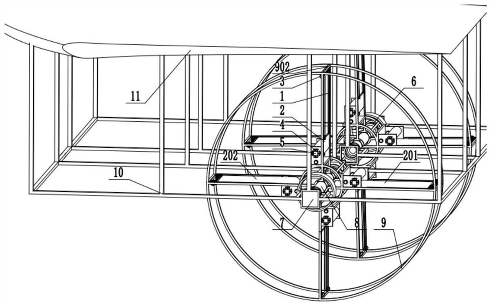
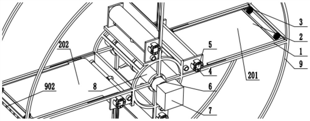
[0034] Example 1: Combining figure 1 , figure 2 , image 3 , Figure 4 , Figure 5 , Image 6 and Figure 7 , a high-voltage wire inspection drone that uses two curtains with fixed wings to drive an energy-adjustable rotary-wing aircraft. It includes a rotating curtain, a second reducer 6, a motor 7, a rotating shaft 8, a fuselage frame 10 and a fixed wing 11. The fuselage frame 10 is symmetrically arranged with two rotating shafts 8 on both sides. Both are perpendicular to the longitudinal plane of symmetry of the aircraft, and the two motors 7 arranged on the fuselage frame 10 respectively drive the two rotating shafts 8 to rotate continuously after being decelerated by the two second reducers 6 arranged on the fuselage frame 10 respectively. Two rotating curtain wings are respectively fixedly connected on two rotating shafts 8; the rotating curtain wing comprises a rotating frame 1, and a curtain wing installed in the rotating frame 1, and the curtain wing comprises ...
Embodiment 2
[0035] Example 2: Combining figure 1 , figure 2 , image 3 , Figure 4 , Figure 5 , Image 6 and Figure 7 , a high-rise building fire-fighting drone that uses two curtains with fixed wings to drive an energy-adjustable rotary-wing aircraft. It includes a rotating curtain, a second reducer 6, a motor 7, a rotating shaft 8, a fuselage frame 10 and a fixed wing 11. The fuselage frame 10 is symmetrically arranged with two rotating shafts 8 on both sides. Both are perpendicular to the longitudinal plane of symmetry of the aircraft, and the two motors 7 arranged on the fuselage frame 10 respectively drive the two rotating shafts 8 to rotate continuously after being decelerated by the two second reducers 6 arranged on the fuselage frame 10 respectively. Two rotating curtain wings are respectively fixedly connected on two rotating shafts 8; the rotating curtain wing comprises a rotating frame 1, and a curtain wing installed in the rotating frame 1, and the curtain wing compri...
PUM
 Abstract
Description
Claims
Application Information
 - R&D Engineer
- R&D Manager
- IP Professional
- Industry Leading Data Capabilities
- Powerful AI technology
- Patent DNA Extraction
Browse by: Latest US Patents, China's latest patents, Technical Efficacy Thesaurus, Application Domain, Technology Topic, Popular Technical Reports.
© 2024 PatSnap. All rights reserved.Legal|Privacy policy|Modern Slavery Act Transparency Statement|Sitemap|About US| Contact US: help@patsnap.com