Eureka AIR delivers breakthrough ideas for toughest innovation challenges, trusted by R&D personnel around the world.
A new energy vehicle charging system
What is Al technical title?
Al technical title is built by PatSnap Al team. It summarizes the technical point description of the patent document.
A new energy vehicle and charging system technology, applied in the field of new energy vehicle charging system, can solve the problems of wasting time, charging for a long time, easy to forget charging time, etc.
Active Publication Date: 2020-08-14
徐州势甲信息科技有限公司
View PDF5 Cites 0 Cited by
Summary
Abstract
Description
Claims
Application Information
AI Technical Summary
This helps you quickly interpret patents by identifying the three key elements:
Problems solved by technology
Method used
Benefits of technology
Problems solved by technology
[0002] New energy vehicles have the characteristics of energy saving and environmental protection, and are being widely promoted. In the existing technology, when charging new energy vehicles, the user needs to put the car in place and then insert the charging plug into the vehicle. When the length of the charging line is not enough, the charging plug cannot When plugged into the charging jack of the car, the user needs to restart the vehicle, adjust the position, and then manually insert the charging plug into the charging jack, and then the user will easily forget the charging time while waiting for charging, resulting in a long time Charging is a waste of time, so a new energy vehicle charging system is needed to solve the above problems
Method used
Image
Click on the blue label to locate the original text in one second.
Reading with bidirectional positioning of images and text.
Examples
Embodiment Construction
[0021] In order to make the technical means, creative features, goals and effects achieved by the present invention easy to understand, the present invention will be further described below in conjunction with specific embodiments.
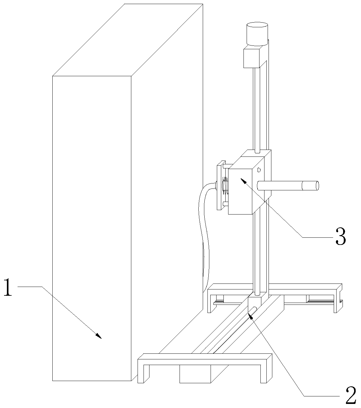
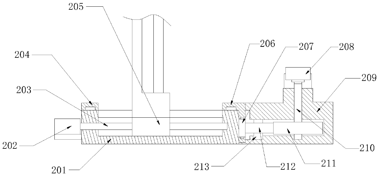
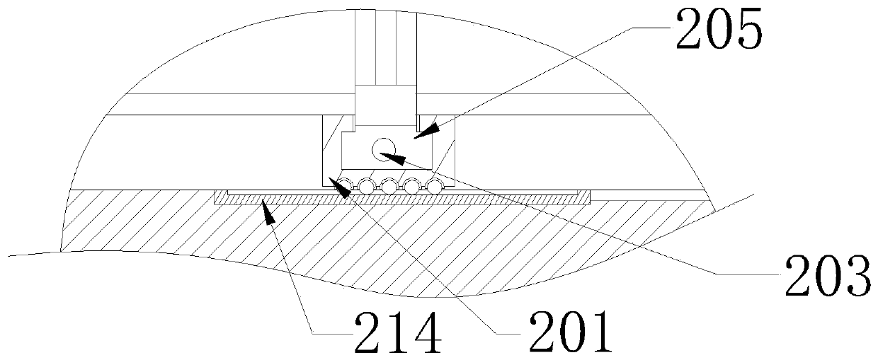
[0022] see Figure 1-Figure 5 , the present invention provides a technical solution: a new energy vehicle charging system, including a charging pile 1, a horizontal moving component 2 and a vertical alignment component 3, the horizontal moving component 2 is installed on the ground on the right side of the charging pile 1, vertically The alignment assembly 3 is installed on the upper end of the horizontal movement assembly 2, and the horizontal movement assembly 2 includes a mounting seat 201, a small motor one 202, a screw mandrel one 203, a front fixing frame 204, a ball nut seat one 205, a rear fixing frame 206, a rack 207, small motor 2 208, fixed seat 209, rotating shaft 1 210, gear 1 211, gear 2 212, rotating shaft 2 213 and base plate 214, ...
PUM
Abstract
The invention provides a new energy vehicle charging system, which includes a charging pile, a horizontal moving component and a vertical alignment component. The horizontal moving component is installed on the ground on the right side of the charging pile, the vertical alignment component is installed at the upper end of the horizontal movement component, the horizontal moving component includes an installation seat, a first small motor, a first screw rod, a front fixing frame, a first ball nut seat, a rear fixing frame, a rack, a second small motor, a fixing seat, a rotating shaft, a first gear, a second gear, a second rotating shaft and a bottom plate, and the vertical alignment component comprises a moving frame, a second lead screw, a charging plug, a cylinder, a carrier, a third small motor (306), a limit frame, a spring, an iron ring and an electromagnet. Compared with the prior art, the new energy vehicle charging system has the following beneficial effects that adjustment of the horizontal position of the charging plug is convenient, adjustment of the vertical position of the charging plug is further convenient, automatic connection and disconnection of the charging plug are realized, and charging completion reminder can be conducted.
Description
technical field [0001] The invention relates to a new energy vehicle charging system, which belongs to the technical field of new energy vehicles. Background technique [0002] New energy vehicles have the characteristics of energy saving and environmental protection, and are being promoted in large quantities. In the existing technology, when charging new energy vehicles, the user needs to put the car in place and then insert the charging plug into the vehicle. When the length of the charging line is not enough, the charging plug cannot When plugged into the charging jack of the car, the user needs to restart the vehicle, adjust the position, and then manually insert the charging plug into the charging jack, and then the user will easily forget the charging time while waiting for charging, resulting in a long time Charging is a waste of time, so a new energy vehicle charging system is needed to solve the above-mentioned problems. Contents of the invention [0003] In vie...
Claims
Application Information
Patent Timeline
Application Date:The date an application was filed.
Publication Date:The date a patent or application was officially published.
First Publication Date:The earliest publication date of a patent with the same application number.
Issue Date:Publication date of the patent grant document.
PCT Entry Date:The Entry date of PCT National Phase.
Estimated Expiry Date:The statutory expiry date of a patent right according to the Patent Law, and it is the longest term of protection that the patent right can achieve without the termination of the patent right due to other reasons(Term extension factor has been taken into account ).
Invalid Date:Actual expiry date is based on effective date or publication date of legal transaction data of invalid patent.