Thermal bimetal tension driver and preparation method thereof
A thermal bimetal driver technology, applied in the direction of instruments, scientific instruments, measuring devices, etc., can solve the problems of difficult mass production, cumbersome preparation, complex structure of thermal bimetal drivers, etc., and achieve the effect of simple structure and convenient preparation
- Summary
- Abstract
- Description
- Claims
- Application Information
AI Technical Summary
Problems solved by technology
Method used
Image

Examples
Embodiment 1
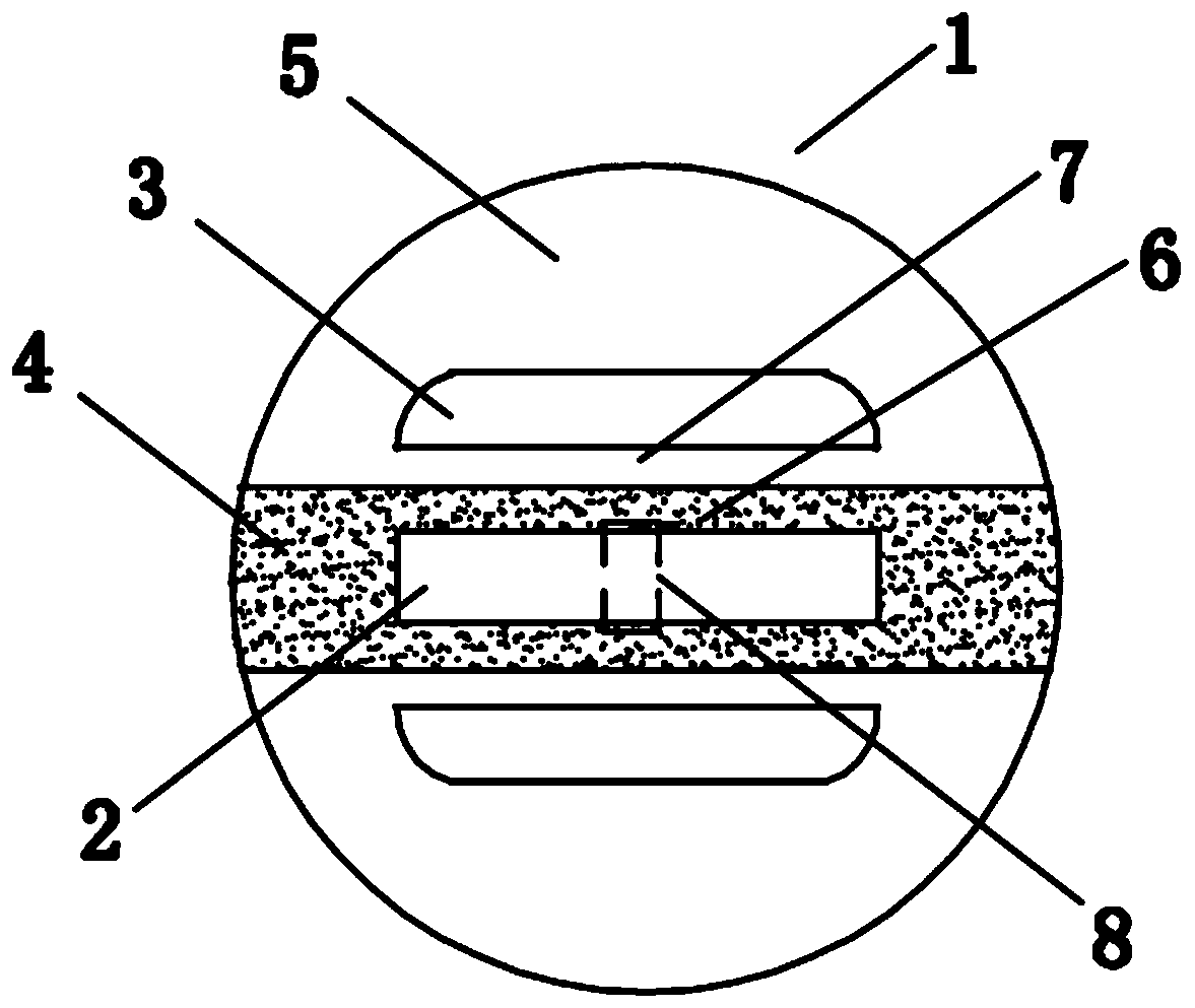
[0045] see figure 1 , this embodiment provides a thermal bimetal tension driver, including a sheet body 1 and a first opening 2 and a second opening 3 opened on the body 1;
[0046] The body 1 includes an active area 4 and a passive area 5 arranged on both sides of the active area 4, the thermal expansion coefficient of the material used in the active area 4 is greater than that of the material used in the passive area 5;
[0047] The first opening 2 is located in the active area 4, and the second opening 3 is located in the passive area 5;
[0048] A first opening 2 is provided in the active area 4, a second opening 3 is provided in each of the two passive areas 5, and the two second openings 3 are symmetrically arranged on both sides of the first opening 2;
[0049] The connecting portion between the first opening 2 and the passive area 5 is set as a first carrying beam 6, the connecting portion between the second opening 3 and the active area 4 is set as a second carrying ...
Embodiment 2
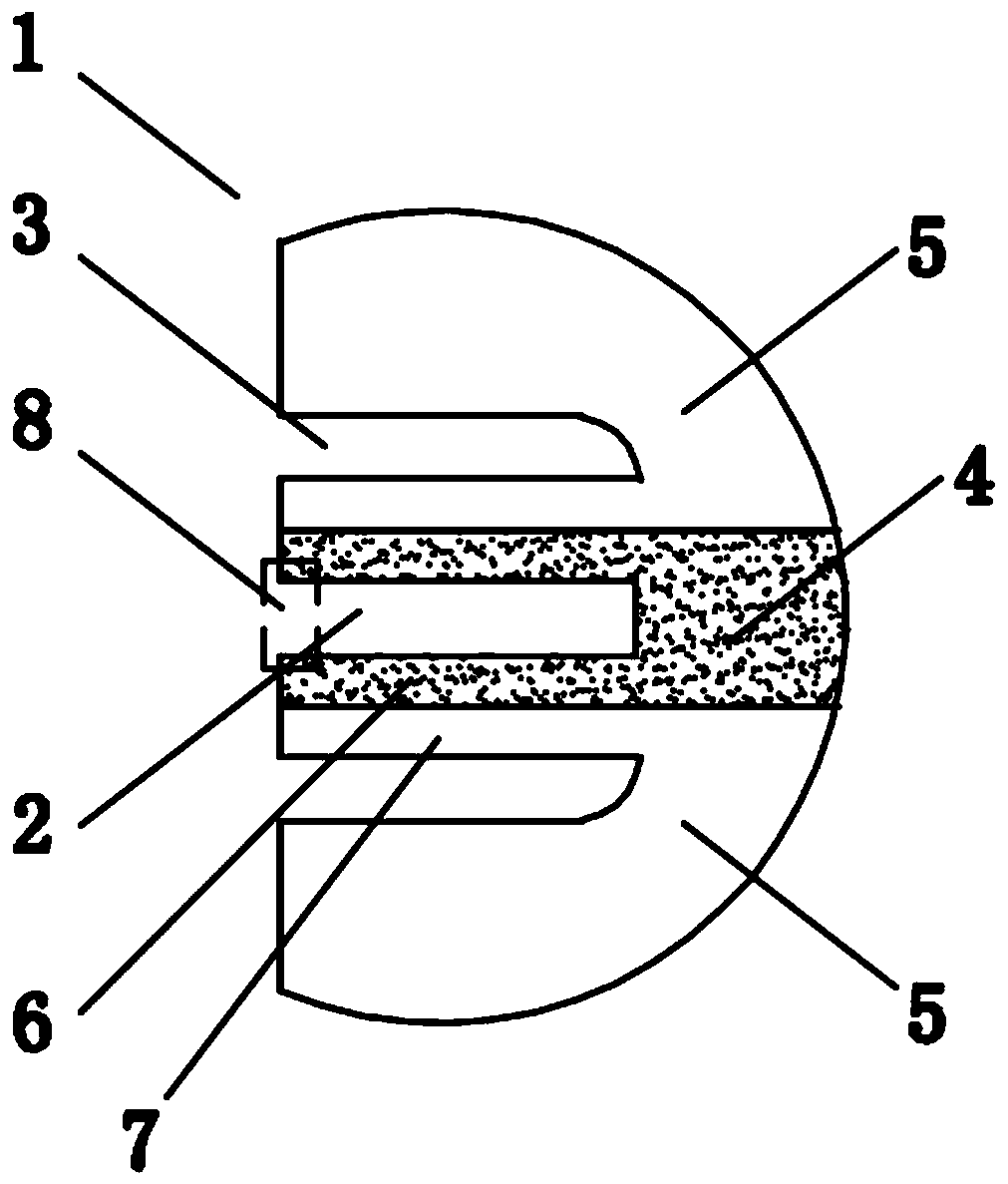
[0055] This embodiment is based on Embodiment 1, and the difference is that in this embodiment, the first opening 2 and the two second openings 3 are open on the same side of the body 1, see figure 2 .
[0056] Depend on figure 2 As shown, the body 1 has a semicircular sheet structure, and the open ends of the first opening 2 and the two second openings 3 are all facing the linear side of the body 1, which makes the two first carrying beams 6 and the two second The two carrying beams 7 are both configured as a cantilever structure, and the ends of the first carrying beam 6 and the second carrying beam 7 that are away from the fixed connection on the body 1 are set as the suspension ends. Since the coefficient of thermal expansion of the first carrying beam 6 is greater than that of the second carrying beam 7, when heated, the suspension ends of the two first carrying beams 6 will bend toward one side of the second carrying beam 7, i.e. A tension driving position 8 can be f...
Embodiment 3
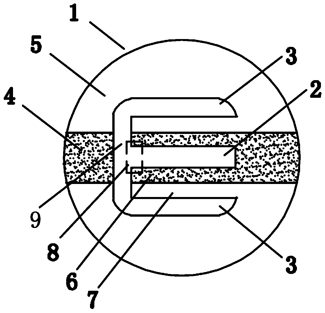
[0059] This embodiment is based on Embodiment 1, and the difference is that the same side ends of the first opening 2 and the two second openings 3 communicate through a connecting channel 9, and the first opening 2, the The second openings 3 are respectively perpendicular to the connecting channels 9, see image 3 .
[0060] Depend on image 3 It can be seen that the body 1 has a circular plate structure, and the connecting channel 9 is arranged in the body 1, and the two first carrying beams 6 and the two second carrying beams 7 are both set as cantilever structures. When heated, the two The suspension ends of the first carrying beams 6 all bend towards one side of the second carrying beams 7, that is, a stretching driving position 8 can be formed between the suspension ends of the two first carrying beams 6, so that in this embodiment The thermal bimetal driver in this example can be called a closed tension driver.
[0061] At the same time, since the two first carrying ...
PUM
| Property | Measurement | Unit |
|---|---|---|
| thickness | aaaaa | aaaaa |
| diameter | aaaaa | aaaaa |
Abstract
Description
Claims
Application Information
 - R&D
- Intellectual Property
- Life Sciences
- Materials
- Tech Scout
- Unparalleled Data Quality
- Higher Quality Content
- 60% Fewer Hallucinations
Browse by: Latest US Patents, China's latest patents, Technical Efficacy Thesaurus, Application Domain, Technology Topic, Popular Technical Reports.
© 2025 PatSnap. All rights reserved.Legal|Privacy policy|Modern Slavery Act Transparency Statement|Sitemap|About US| Contact US: help@patsnap.com