Protection device for bulged beam body, and mounting method of protection device
A technology of a protective device and an installation method, which is applied in the processing of building materials, construction, building structure, etc., can solve the problems of scratching and wearing of the beam, affecting the appearance, and damage caused by bumping, so as to achieve easy installation and disassembly, and a simple structure. , The effect of preventing scratches and bumps
- Summary
- Abstract
- Description
- Claims
- Application Information
AI Technical Summary
Problems solved by technology
Method used
Image
Examples
Embodiment 1
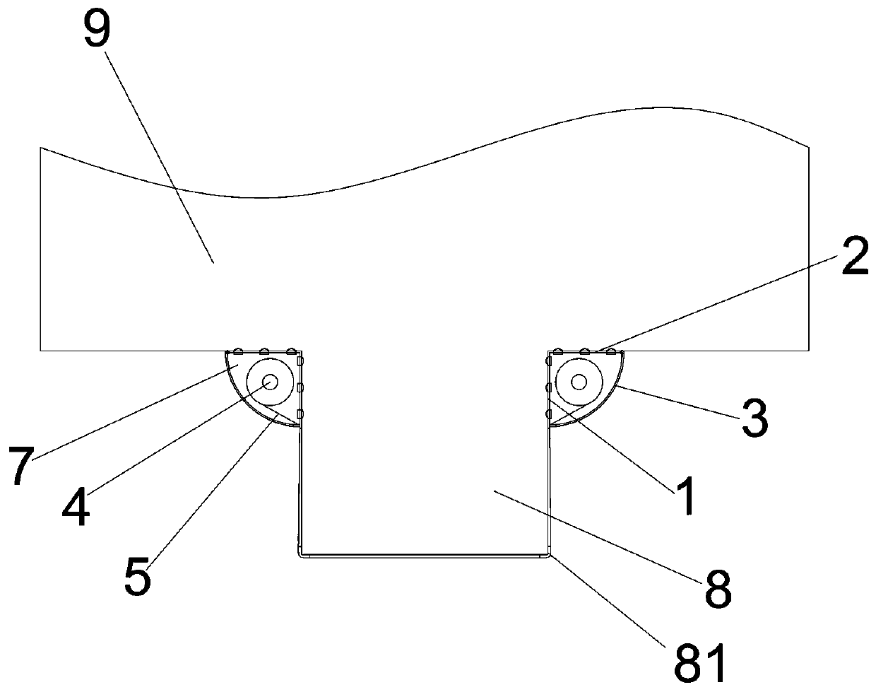
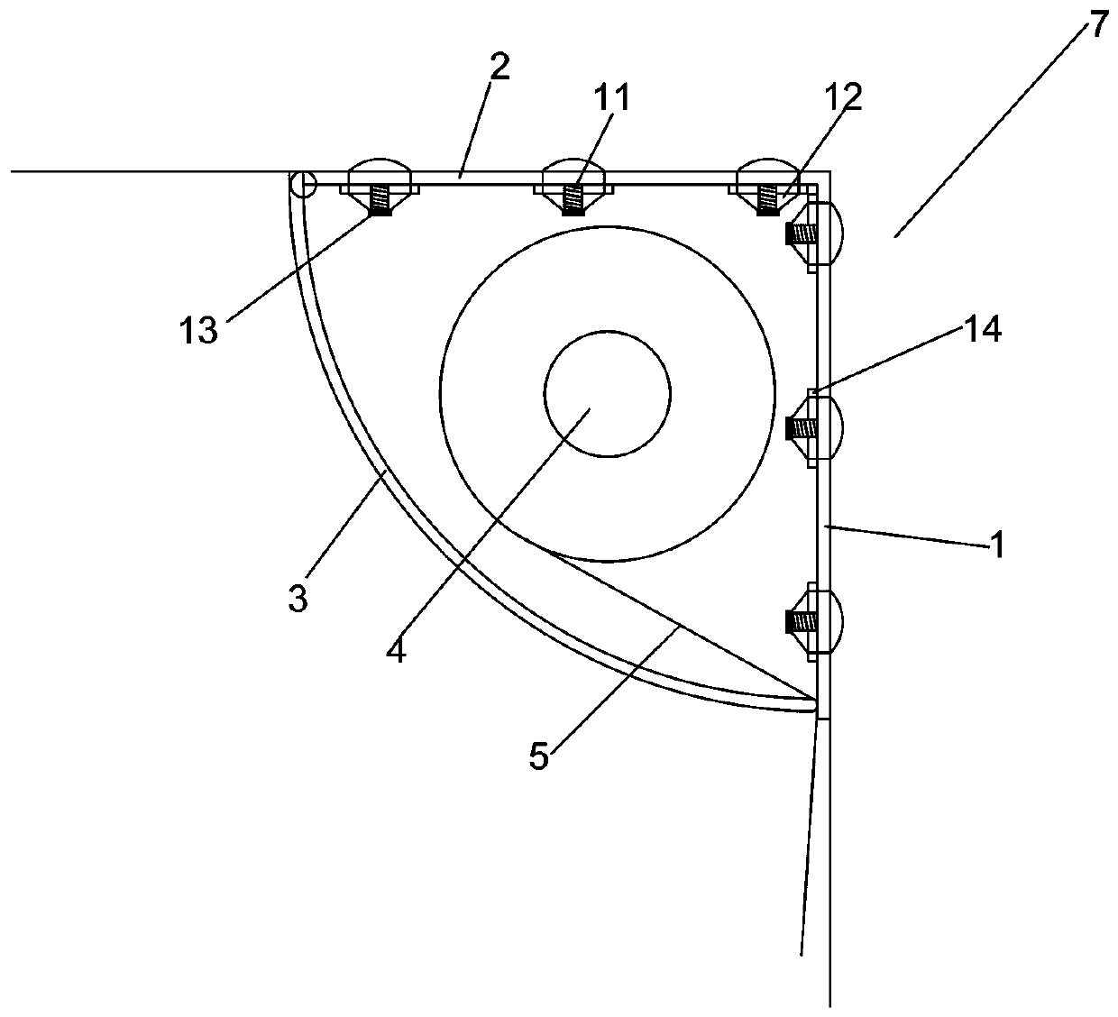
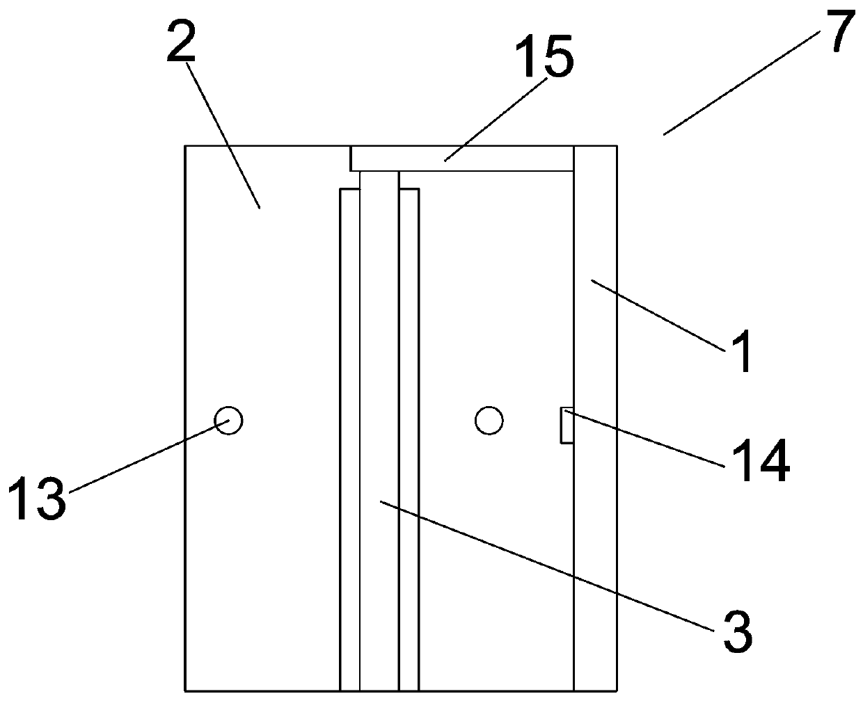
[0032] Embodiment one: if Figures 1 to 3 As shown, it is only one of the embodiments of the present invention, a protective device protruding from the beam body, including the installation part 7 arranged at the junction of the beam body 8 and the wall body 9, and the installation part 7 includes the The first plate body 1 connected to the beam body 8, the second plate body 2 connected to the wall body 9, and the rotating cover 3 connected to the side of the second plate body 2 away from the first plate body 1, so The rotating cover 3 rotates around the connection with the second plate body 2, and a winding roller 4 is arranged in the space surrounded by the first plate body 1, the second plate body 2 and the rotating cover 3, and the installation The number of parts 7 is two, and the protective cloth 5 is connected between the winding rollers 4 of the two installation parts 7 .
[0033] In the present invention, the two installation parts 7 are respectively installed at the...
Embodiment 2
[0039] Embodiment two, still as Figures 1 to 3 As shown, it is only one of the embodiments of the present invention. In order to make the protection effect of a protective device protruding from the beam body of the present invention better and the degree of stability higher, the present invention also has the following design:
[0040] First of all, the number of the mounting holes is at least one. In fact, at least one mounting hole is provided on the first plate body 1 and the second plate body 2. The plate body 2 is fixed, so that the stability of the mounting part 7 is better.
[0041] In addition, the end of the rotating cover 3 away from the second plate body 2 is arc-shaped. In fact, when the rotating cover 3 is closed, the end of the rotating cover 3 away from the second plate body 2 and the first plate body 1 contact, and the protective cloth 5 is also derived from the side of the first plate body 1, in order to facilitate the winding of the protective cloth 5, the...
Embodiment 3
[0046] Embodiment three, such as Figure 4 As shown, it is only one of the embodiments of the present invention, and the present invention also provides a method for installing a protective device protruding from the beam body, including the following steps:
[0047] S1: Reserve an installation space for the installation part at the two joints of the beam body and the wall body;
[0048] S2: Fix the first plate body, the second plate body and the rotating cover of the installation part;
[0049] S3: The two ends of the protective cloth are respectively wound to two winding rollers, and the winding rollers are clamped into the space surrounded by the first plate body, the second plate body and the rotating cover;
[0050] S4: Rotate the winding roller, tighten the protective cloth, and close the rotating cover.
[0051] Certainly, when step S2 is executed, mounting holes are provided on the first plate body and the second plate body, and the drilling bits at the mounting hole...
PUM
 Abstract
Description
Claims
Application Information
 - R&D
- Intellectual Property
- Life Sciences
- Materials
- Tech Scout
- Unparalleled Data Quality
- Higher Quality Content
- 60% Fewer Hallucinations
Browse by: Latest US Patents, China's latest patents, Technical Efficacy Thesaurus, Application Domain, Technology Topic, Popular Technical Reports.
© 2025 PatSnap. All rights reserved.Legal|Privacy policy|Modern Slavery Act Transparency Statement|Sitemap|About US| Contact US: help@patsnap.com


