A diaphragm coupling of triple diaphragm group

A diaphragm coupling and diaphragm group technology, which is applied in the direction of shaft couplings, elastic couplings, mechanical equipment, etc., can solve the problems of poor displacement compensation, diaphragm fatigue damage, and limited application range of couplings, etc. question

Active Publication Date: 2021-05-25
LUDONG UNIVERSITY
View PDF6 Cites 0 Cited by
  • Summary
  • Abstract
  • Description
  • Claims
  • Application Information

AI Technical Summary

Problems solved by technology

However, due to the unreasonable structure of the existing diaphragm coupling, the angular displacement, axial displacement, and radial displacement that can be compensated sometimes cannot meet the needs of users; or when the coupling is in a large angular Under the repeated action of displacement, axial displacement and radial displacement, the diaphragm is prone to fatigue damage
The diaphragm couplings of the existing structure either cannot adapt to large angular displacement, axial displacement, and radial displacement, which limits the application range of the coupling, or cannot effectively reduce the additional displacement caused by the additional displacement. The load on the diaphragm directly affects the performance and service life of the coupling
In order to solve these problems, researchers have developed structures such as patch diaphragm couplings, that is, a compensation structure is provided locally at the connection between the diaphragm group and the half-coupling, and the displacement is compensated by the local deformation of the diaphragm group, but Couplings with this type of structure still have the problem of poor compensation for displacement, so it is necessary to invent a diaphragm coupling with a more reasonable structure

Method used


Image

  • A diaphragm coupling of triple diaphragm group
  • A diaphragm coupling of triple diaphragm group
  • A diaphragm coupling of triple diaphragm group

Examples


Embodiment 1

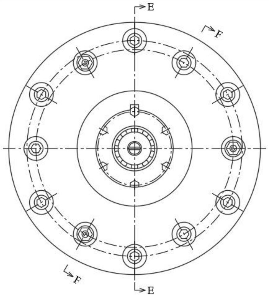
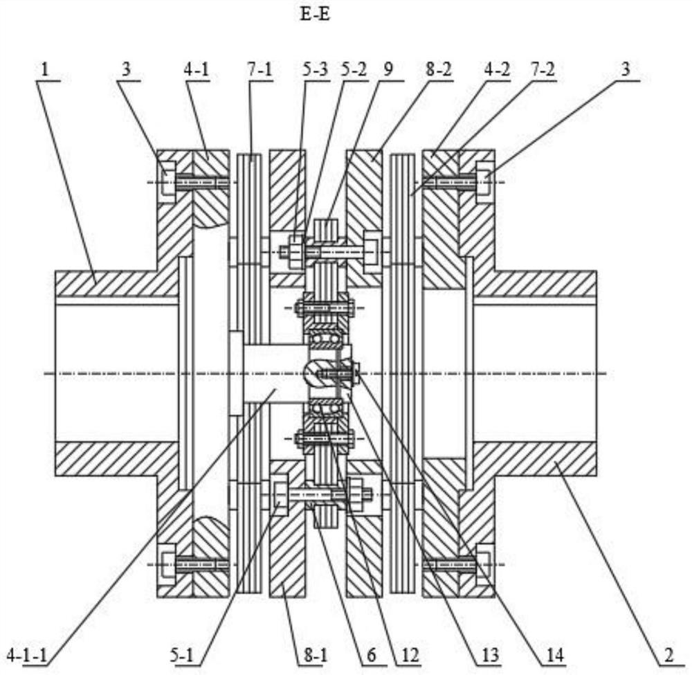
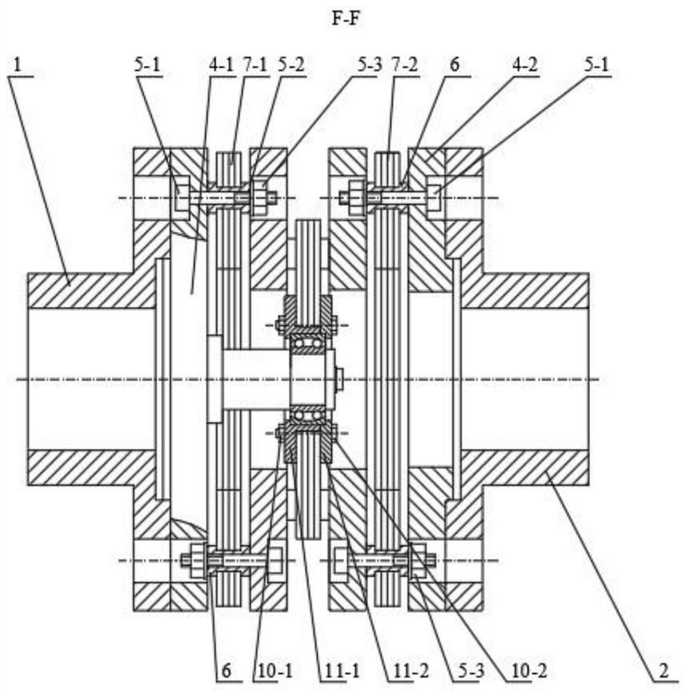
[0037] Embodiment 1, reference figure 1 , figure 2 , image 3 , Figure 4 , Figure 5 , Image 6 , Figure 7 , Figure 8 , Figure 9 , Figure 10 , Figure 11 , Figure 12 , Figure 13 , Figure 14 , Figure 15 , Figure 16 , Figure 17 , Figure 18 , Figure 19 , Figure 20 , Figure 21 , Figure 22 , Figure 23 , Figure 24 , Figure 25 , Figure 26 , Figure 27 , Figure 28 , Figure 29 , Figure 30 , Figure 31. It can be seen from the accompanying drawings that a diaphragm coupling of a triple diaphragm group is composed of a first half coupling 1, a second half coupling 2, a half coupling fixing screw 3, and a first membrane coupling method. Lan 4-1, second diaphragm flange 4-2, diaphragm group connecting bolt 5-1, diaphragm group connecting bolt gasket 5-2, diaphragm group connecting bolt nut 5-3, diaphragm group fixing sleeve 6. The first diaphragm group 7-1, the second diaphragm group 7-2, the first intermediate connecting flange 8-1, t...


PUM


Abstract

The invention discloses a diaphragm coupling of a triple diaphragm group. Because the diaphragm coupling of the existing structure cannot adapt to large angular displacement, axial displacement, and radial displacement, the application range of the coupling is limited, or the additional displacement caused by the additional displacement cannot be effectively reduced. The load on the diaphragm directly affects the performance and service life of the coupling. In order to solve these problems, a triple diaphragm group structure is invented, and the middle diaphragm group is fixedly connected with the self-aligning bearing, so that the self-aligning performance of the self-aligning ball bearing can be used to reduce the effect on the diaphragm due to additional displacement. The additional load, so as to achieve the compensation of large angular displacement, axial displacement, radial displacement, and greatly improve the service life of the diaphragm coupling.

Description

technical field [0001] The invention relates to a coupling of a mechanical transmission device, which is a coupling device for movement and power transmission between a prime mover (such as an electric motor, an internal combustion engine, etc.) and a working machine (such as a pump, a reducer, etc.), and belongs to the technical field of mechanical transmission . Background technique [0002] Couplings are widely used in rotating machinery, including rigid couplings and elastic couplings. Diaphragm coupling is a new type of coupling, which has the advantages of transmitting large torque, allowing large displacement error, allowing high-speed rotation, mitigating impact vibration, generally does not need lubrication, and is easy to install and maintain. It is widely used in National defense, shipbuilding, aviation, petrochemical, vehicles, machinery and other industries can replace gear couplings, elastic sleeve pin couplings and other coupling devices. However, due to the...

Claims


Application Information

Patent Timeline
Patent Type & Authority Patents(China)
IPC IPC(8): F16D3/56
CPCF16D3/56
Inventor 王亮申陈燕王昕彦田忠民王晓晨
Owner LUDONG UNIVERSITY
Why Eureka
Try Eureka