
Detection method for image defect of receiver product and detection light source thereof

A detection method and receiver technology, applied in sorting and other directions, can solve the problems that the pit edges cannot be displayed, the slope-shaped pits cannot be displayed, and the pit edges are not obvious, so as to save the manual detection process and save detection The effect of cost and easy operation

Inactive Publication Date: 2019-09-13
BEIJING FOCUSIGHT TECH
View PDF6 Cites 1 Cited by
  • Summary
  • Abstract
  • Description
  • Claims
  • Application Information

AI Technical Summary

Problems solved by technology

[0004] The light source in the prior art is an ordinary coaxial light source, which cannot show gentle slope-shaped pits on the image, and the dirt defects and pit defects captured in the same form cannot be distinguished
Due to the lack of sharpness of the gentle slope pit, the edge of the pit is not obvious, and the ordinary coaxial light source cannot show the edge of the pit; the edge of the sharp pit is obvious, which can be shown by the ordinary coaxial light source, and the pit part is more than flat The area is dark, but the dirt also appears darker than the flat area under the same light source, making the dirt defect and the pit defect indistinguishable

Method used


Image

  • Detection method for image defect of receiver product and detection light source thereof
  • Detection method for image defect of receiver product and detection light source thereof
  • Detection method for image defect of receiver product and detection light source thereof

Examples


Embodiment 1

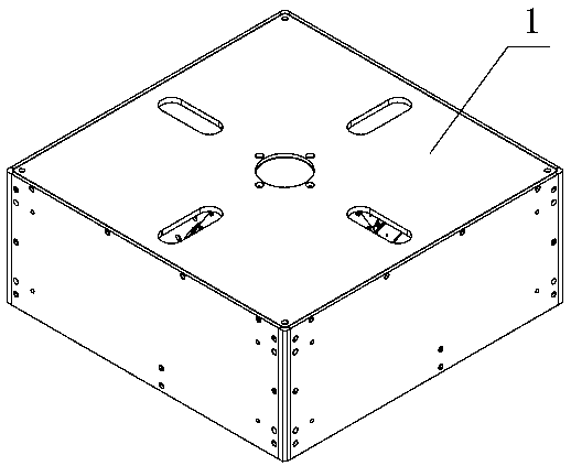
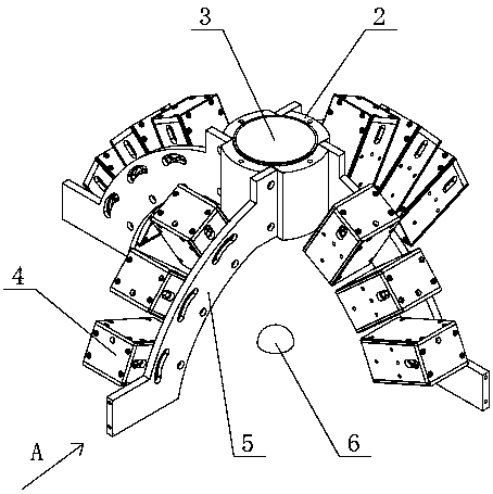
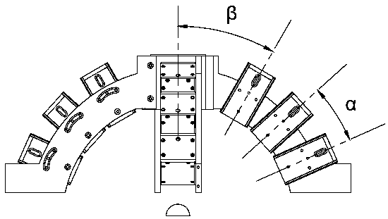
[0027] like Figure 1-3 Shown is a light source for detecting imaging defects of receiver products. The detection light source has a cross-shaped light source fixing bracket, and the outer cover of the light source fixing bracket is provided with a housing 1. The fixing seat 2 in the center of the bracket, the fixing seat 2 is fixedly connected with the housing 1 through screws so as to fix the light source fixing bracket with the housing 1, and the outer wall of the fixing seat 2 is evenly fixed with four downwardly curved curved fixing plates 5, The center of the fixing seat 2 is provided with a camera shooting hole 3, and a light source group is installed on the fixing plate 5. The light source group includes several coaxial light sources 4, and the distance between the central axes of two adjacent coaxial light sources 4 on the same fixing plate 5 The included angle α is 18°, and the included angle β between the central axis of the coaxial light source 4 close to the fixed...


PUM


Abstract

The invention relates to the technical field of image defect detection, in particular to a detection method for an image defect of a receiver product and a detection light source thereof. The detection method for the image defect of the receiver product is to detect the image defect of the receiver product by using the detection light source, and the detection method comprises the following stepsof (1) debugging the light source; (2) setting light source parameters; (3), collecting images; (4), image processing; and (5), dividing a warehouse for the product. In the invention, the collected image is subjected to image processing by a photometric stereo vision algorithm, so that the gentle slope pit defect is detected, and the image forming mode displays the height information, so the dirtydefect is not presented in the image, and the pit defect rather than the dirty defect can be detected only; the influence of the dirty defect is avoided; the pit defect of the receiver product can beautomatically detected in batches, the manual inspection process is eliminated, and the detection efficiency is improved and the detection cost is saved.

Description

technical field [0001] The invention relates to the technical field of imaging defect detection, in particular to a method for detecting imaging defects of receiver products and a detection light source thereof. Background technique [0002] Photometric stereo vision technology analyzes the three-dimensional shape information of objects through two-dimensional surface texture. This technology requires at least three light sources with different angles to image the same object, and the angle of the light source must be fixed and unchangeable. Although photometric stereo vision can perform 3D surface reconstruction in the form of relative height maps, it is not suitable for high-precision absolute 3D measurement or reconstruction applications. This can cause errors if the light source does not have parallel rays with a uniform intensity distribution or if the surface of the object does not have Lambertian reflection properties. Photometric stereo vision assumes parallel ligh...

Claims


Application Information

Patent Timeline
Patent Type & Authority Applications(China)
IPC IPC(8): B07C5/342B07C5/36
CPCB07C5/3422B07C5/361
Inventor 都卫东王岩松吴健雄赵梦逸张佳俊
Owner BEIJING FOCUSIGHT TECH
Learn More