
Control circuit of normally-on emergency lamp

A technology for controlling circuits and emergency lights, applied in the field of emergency lights, can solve problems such as high idle rate, waste of resources, and troublesome maintenance of emergency lights

Pending Publication Date: 2019-09-10
XIAMEN YANKON ENERGETIC LIGHTING CO LTD
View PDF0 Cites 1 Cited by
  • Summary
  • Abstract
  • Description
  • Claims
  • Application Information

AI Technical Summary

Problems solved by technology

Therefore, the utilization rate of emergency lights is very low and the idle rate is high, resulting in a waste of resources
And it is more troublesome to overhaul the emergency lights

Method used


Image

  • Control circuit of normally-on emergency lamp
  • Control circuit of normally-on emergency lamp
  • Control circuit of normally-on emergency lamp

Examples


Embodiment 1

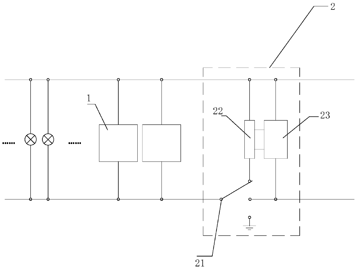
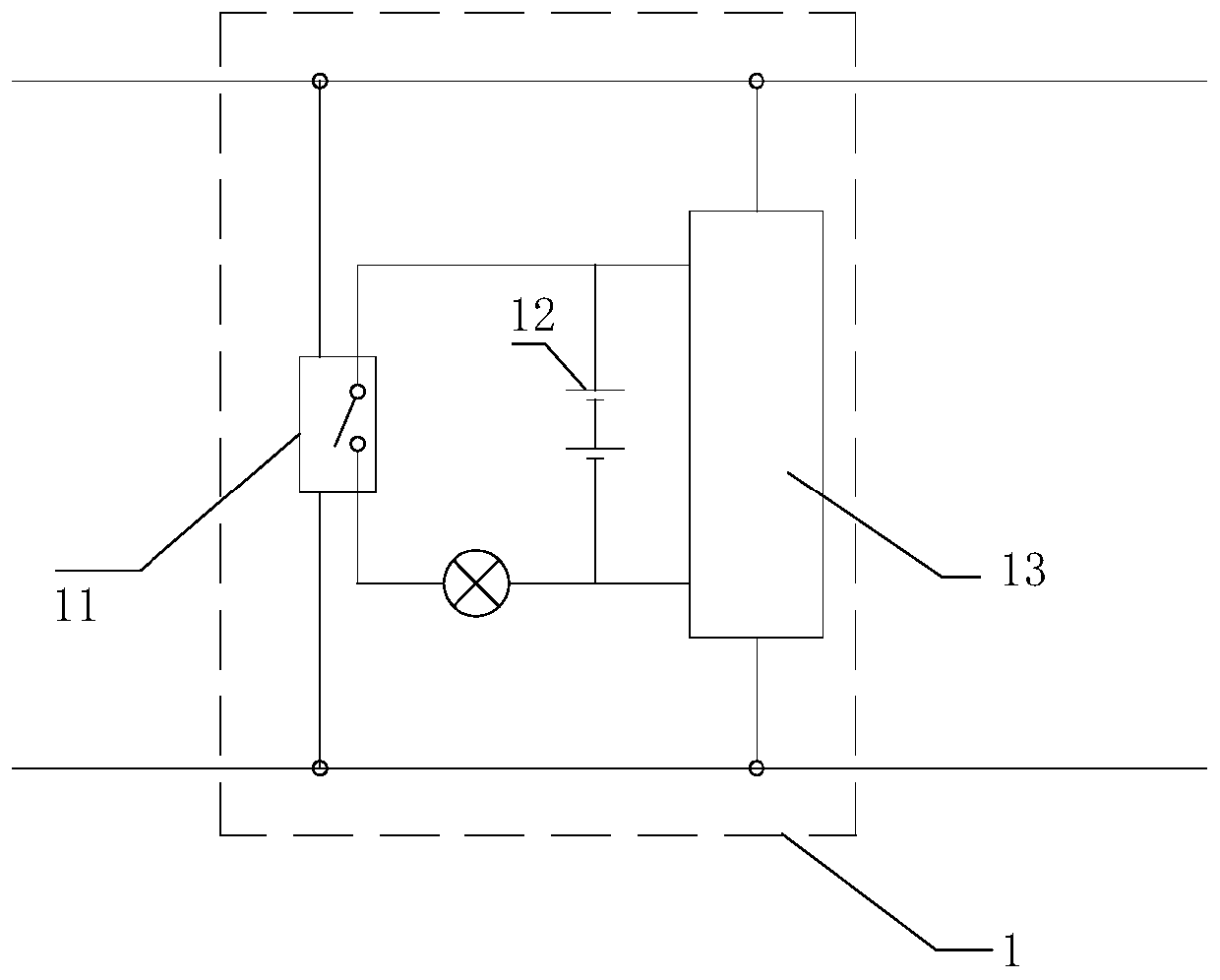
[0025] refer to figure 1 with figure 2 , a control circuit of a constant-on emergency light, comprising: an emergency light driving part 1 and a master switch part 2;

[0026] The main switch part 2 includes a switch 21 arranged on the live wire, a signal generating module 22 and a first rectifying and transforming module 23; the first rectifying and transforming module 23 converts commercial power into direct current and gives the signal The generating module 22 supplies power; the first gear of the switch 21 is used to connect the signal generating module 22 to the emergency light driving part 1, and the second gear is used to disconnect the signal generating module 22 from the emergency light driving part 1;

[0027] The emergency light driving part 1 includes a signal recognition switch 11 and a backup power supply 12; when the signal recognition switch 11 does not receive the signal output by the signal generating module 22, the signal recognition switch 11 is in a clos...

Embodiment 2

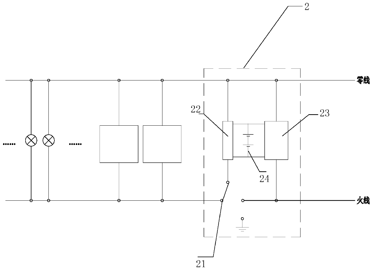
[0036] refer to image 3 , in this embodiment, the main switch part 2 also includes a second backup power supply 24, and when the mains power is normally cut off, the second backup power supply 24 supplies power to the signal generating module 22, and turns the switch 21 in second gear.

[0037] When the three-position switch 21 is in the second gear position, the signal generating module 22 is connected to the emergency light driving part 1; at this time, if the mains is powered on normally, the signal generating module 22 normally sends a signal, and the signal identification switch 11 is disconnected , the emergency light goes out; if the mains power is cut off, the second backup power supply 12 drives the signal sending module to continue sending signals, the signal recognition switch 11 is turned off, and the emergency light goes out.

[0038] This structure realizes that the emergency light is always turned on when the switch 21 is in the first gear position, and is alw...


PUM


Abstract

The invention provides a control circuit of a normally-on emergency lamp, which comprises an emergency lamp driving part and a main brake switch part. The main brake switch part includes a switch arranged on a live wire, and a signal generation module and a first rectification and voltage transformation module. The first rectification and voltage transformation module converts a mains supply intoDC power and supplies power to the signal generation module. A first gear of the switch is used to connect the signal generation module with the emergency lamp driving part, and a second gear is usedto disconnect the signal generation module from the emergency lamp driving part. The emergency lamp driving part includes a signal recognition switch and a standby power supply. When the signal recognition switch does not receive a signal from the signal generation module, the signal recognition switch is in an off state, and the emergency lamp is turned on by taking power from the mains supply orthe standby power supply.

Description

technical field [0001] The invention relates to the field of lighting, in particular to an emergency light. Background technique [0002] Conventional lamps are extinguished due to loss of grid power supply in emergency situations (such as accidental power failures such as fires and earthquakes). Conventional emergency lamps, which light up as emergency lighting when the circuit is open, are usually idle, and the internal circuit needs to be opened or checked one by one to see if they are in good condition during maintenance. Therefore, the utilization rate of emergency lights is very low and the idle rate is high, resulting in a waste of resources. And also more troublesome to the maintenance of emergency light. Contents of the invention [0003] The main technical problem to be solved by the present invention is to provide a control circuit of a constant-on emergency light. When the mains is powered on normally, the emergency light is used as a conventional lighting fi...

Claims


Application Information

Patent Timeline
Patent Type & Authority Applications(China)
IPC IPC(8): H05B37/02
CPCH05B47/10
Inventor 张昕陈金水
Owner XIAMEN YANKON ENERGETIC LIGHTING CO LTD
Learn More