
Intelligent building monitoring device based on internet of things

A monitoring device and Internet of Things technology, which is applied in the direction of supporting machines, mechanical equipment, machine platforms/supports, etc., can solve the problem of limited monitoring range of monitors, and achieve the effect of strong adjustment ability and convenient monitoring

Active Publication Date: 2019-09-10
山东诚丰电子工程有限公司
View PDF11 Cites 2 Cited by
  • Summary
  • Abstract
  • Description
  • Claims
  • Application Information

AI Technical Summary

Problems solved by technology

[0003] The present invention provides an intelligent building monitoring device based on the Internet of Things. Its beneficial effect is that the present invention can be installed at right angles to the building wall, so as to facilitate the monitoring of both the front and side surfaces of the building, and solve the problem of traditional monitor monitoring. limited range of issues

Method used


Image

  • Intelligent building monitoring device based on internet of things
  • Intelligent building monitoring device based on internet of things
  • Intelligent building monitoring device based on internet of things

Examples


specific Embodiment approach 1

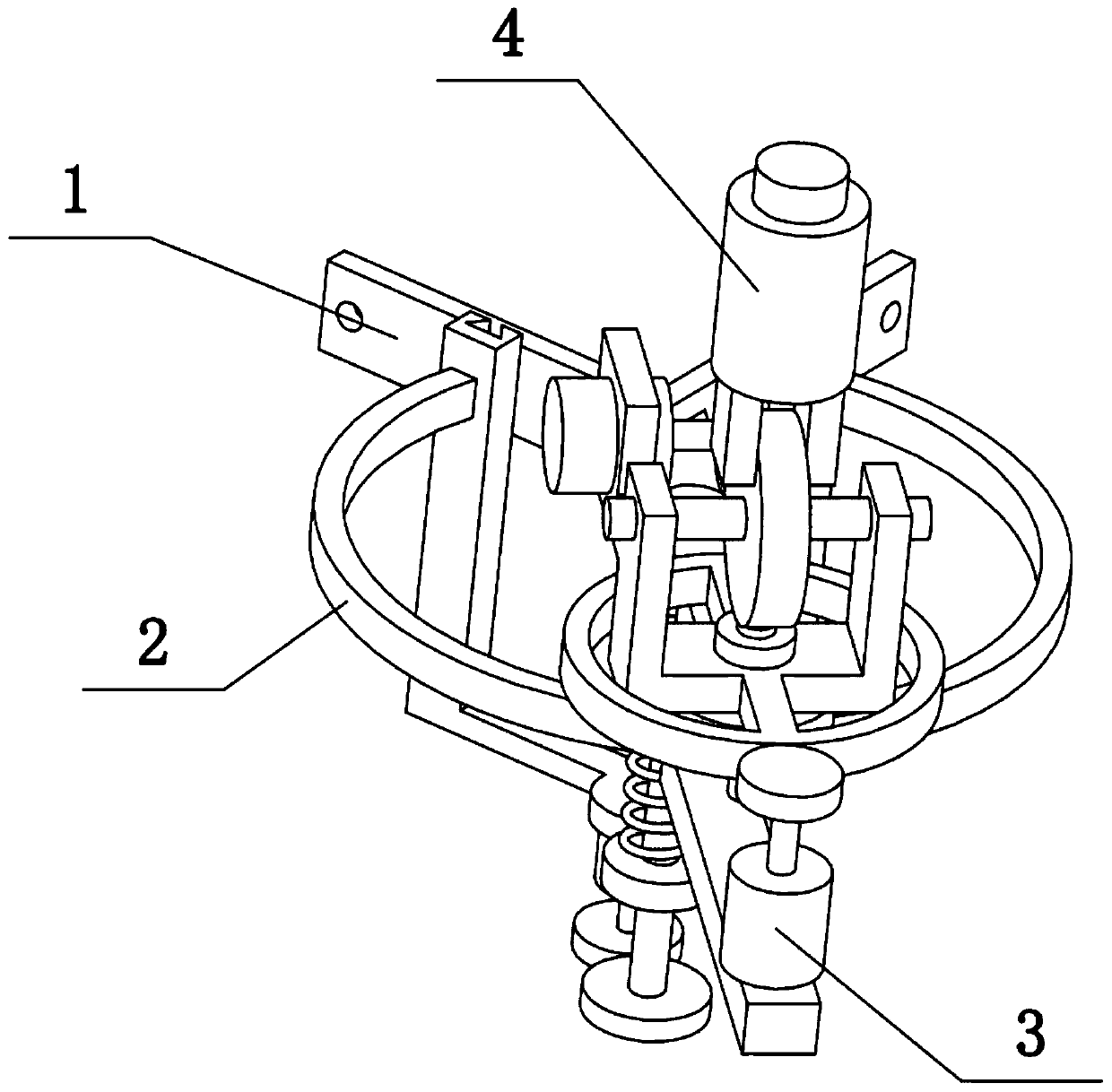
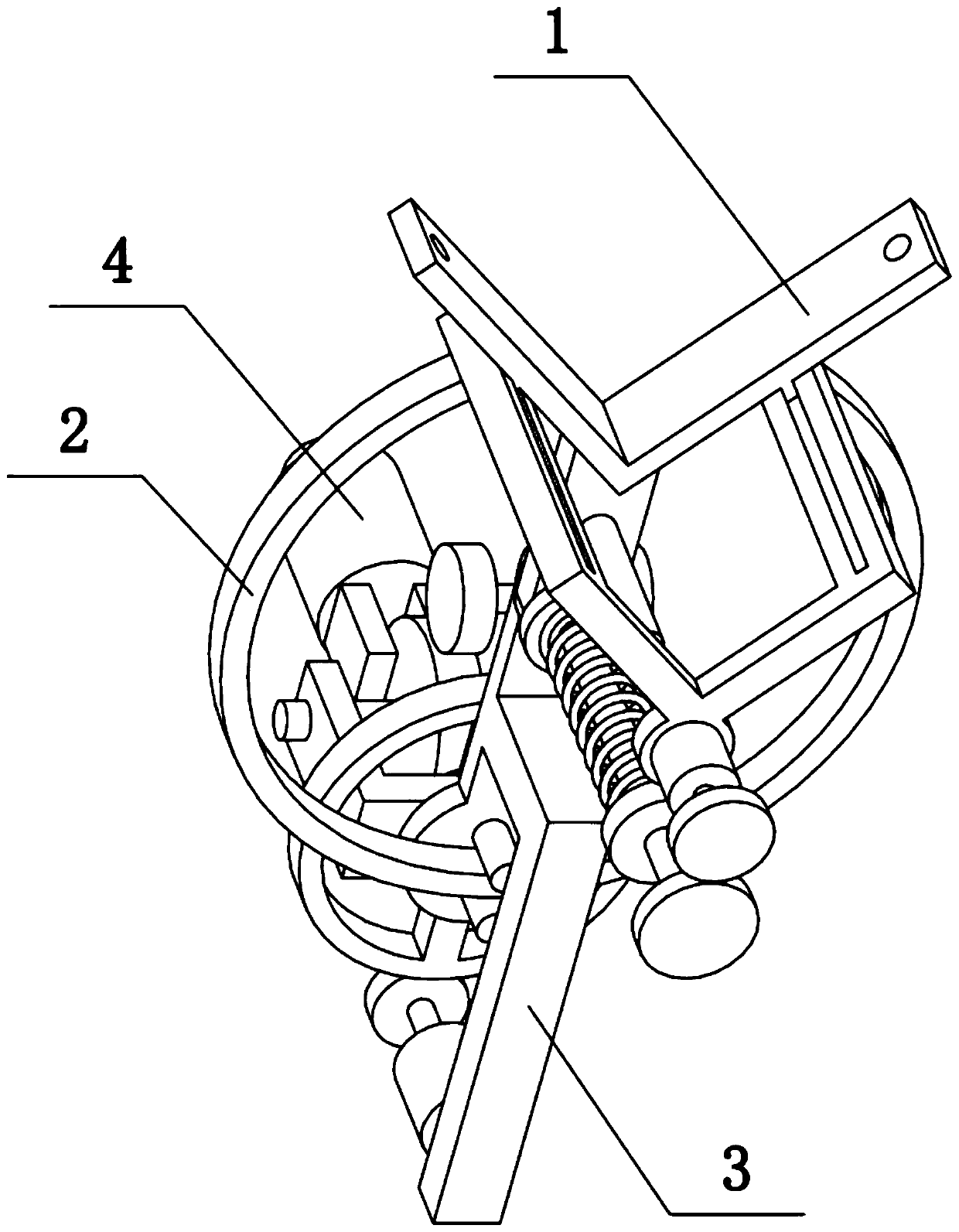
[0036] Combine below Figure 1-10 This embodiment is described. The present invention relates to a monitoring device, more specifically an intelligent building monitoring device based on the Internet of Things, including a fixed frame 1, a floor detection frame 2, a direction swivel frame 3 and a monitor 4. The present invention It can be installed at the right angle of the building wall, and the monitor 4 can rotate along the incomplete ring 2-1, and the rotation range of the monitor 4 is close to 270 degrees, so as to facilitate the monitoring of the front and side of the building. The problem of limited monitoring range of traditional monitors is solved. The monitor 4 can be raised or lowered, so as to pull in the distance from different floors of the building, thereby realizing detailed monitoring of different floors of the building, and can carry out detailed monitoring of the floor conditions on the front and side sides of the building; It solves the problem that the tr...

specific Embodiment approach 2

[0042] Combine below Figure 1-10 To illustrate this embodiment, the telescopic rod 1-3 is a telescopic device such as an electric telescopic rod.

specific Embodiment approach 3

[0044] Combine below Figure 1-10 To illustrate this embodiment, the left and right ends of the right-angle plate 1-1 are provided with screw insertion holes. Screws can be inserted into the screw jacks, and then the right-angle plate 1-1 is fixed at the right angle of the building wall, so as to facilitate the monitoring of the front and side surfaces of the building.


PUM


Abstract

The invention relates to a monitoring device, in particular to an intelligent building monitoring device based on the internet of things. The device comprises a fixing frame, a floor detecting frame,a direction rotating frame and a monitor; and the device can be arranged at a right-angle position of a wall of a building, so that the front face and the side face of the building can be convenientlymonitored, and the problem that the monitoring range of a traditional monitor is limited is solved. According to the device, two trapezoidal convex strips are symmetrically arranged on a right-angleplate, the front end of the right-angle plate is fixedly connected with a front boss, and the lower end of the front boss is fixedly connected with a telescopic rod; and the floor detecting frame comprises an incomplete circular ring, a gear I, a motor I, a bottom frame and vertical sliding rods, wherein the two vertical sliding rods are slidably connected to the two trapezoidal convex strips, thebottom frame is fixedly connected between the lower ends of the two vertical sliding rods, the motor I is fixedly connected to the lower side of the bottom frame, the gear I is fixedly connected to an output shaft at the lower end of the motor I, the incomplete circular ring is fixedly connected between the upper ends of the two vertical sliding rods, and the lower end of the telescopic rod is fixedly connected to the bottom frame.

Description

technical field [0001] The invention relates to a monitoring device, in particular to an intelligent building monitoring device based on the Internet of Things. Background technique [0002] The application number is CN201810694049.X, which discloses a monitor that can be remotely controlled. The invention discloses a monitor that can be remotely controlled. There are infrared devices around the front of the monitor, which are embedded and connected to the main body of the monitor device. The infrared device can receive remote control information to control the main body of the monitor device. The top of the rotating support is provided with an angle adjustment knob. It is movably connected to the rotating support, and the angle adjustment knob can adjust the angle of the main body of the monitor device. The top of the monitor base is provided with a rotating platform, which is movably connected to the monitor base. The rotating platform improves the monitoring In order to ...

Claims


Application Information

Patent Timeline
IPC IPC(8): F16M13/02F16M11/04F16M11/08F16M11/10F16M11/18
CPCF16M11/046F16M11/08F16M11/10F16M11/18F16M13/02
Inventor 郭春龙
Owner 山东诚丰电子工程有限公司
Learn More