
Liquid flow guide member

A technology for guiding components and liquids, which can be used in transmission parts, belts/chains/gears, mechanical equipment, etc., and can solve problems such as high cost and poor effect.

Pending Publication Date: 2019-09-10
SHAANXI FAST GEAR CO
View PDF0 Cites 0 Cited by
  • Summary
  • Abstract
  • Description
  • Claims
  • Application Information

AI Technical Summary

Problems solved by technology

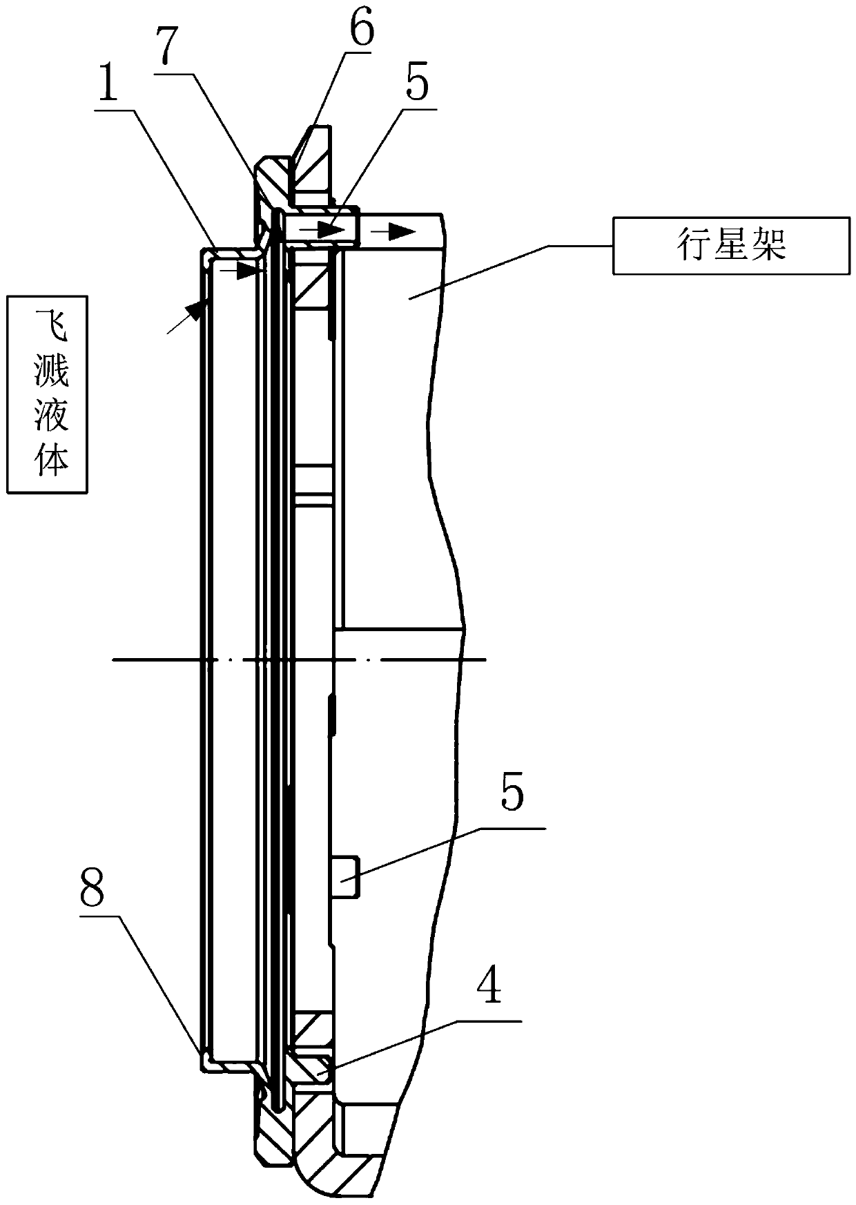
[0006] The purpose of the present invention is to provide a liquid guide member to solve the problem of high cost or poor effect of the prior art method for lubricating planetary gears in automatic transmissions

Method used


Image

  • Liquid flow guide member
  • Liquid flow guide member
  • Liquid flow guide member

Examples


Embodiment Construction

[0024] In order to make the purpose, advantages and features of the present invention clearer, a liquid guiding member proposed by the present invention will be further described in detail below in conjunction with the accompanying drawings and specific embodiments. Advantages and features of the present invention will be apparent from the following description and claims. It should be noted that: the drawings are all in a very simplified form and use inaccurate proportions, which are only used to facilitate and clearly illustrate the purpose of the embodiments of the present invention; secondly, the structures shown in the drawings are often actual structures part; again, each drawing needs to display different emphasis points, and sometimes adopts different scales.

[0025] see Figure 1 to Figure 4 , this embodiment provides a liquid guiding member for lubricating planetary gears in an automatic transmission, comprising: an annular body, a protruding ring 1 is provided on ...


PUM


Abstract

The invention discloses a liquid flow guide member. The liquid flow guide member is used for lubricating a planetary gear in an automatic transmission, and comprises an annular body, wherein a bulgedring is arranged at one side of the annular body, and the sidewall of the bulged ring has a reducing taper in the axial direction; a plurality of hollow guide columns are arranged at the other side ofthe annular body; and an annular groove is formed in the inner wall of the annular body in the radial direction, and the hollow guide columns communicate with the sidewall of the annular groove. In the liquid flow guide member, during the rotary working of the liquid flow guide member, a splashing liquid medium is subjected to flow guide by the bulged ring which has the reducing taper under a centrifugal effect and effectively collected through the annular groove to be pressurized, and then flows to the planetary gear via the hollow guide columns, efficient lubrication in a transmission partlimited by a space is realized, and an independent oil supply system is not needed, so that the purposes of low cost and good lubrication effect are achieved.

Description

technical field [0001] The invention relates to the technical field of gearbox components, in particular to a liquid guiding member. Background technique [0002] The internal lubrication method of the automatic transmission is mainly the splash lubrication of the liquid medium when the gear parts and the hub parts rotate. It turns into small drops and brings them to the friction pair to form automatic lubrication, or it is concentrated in the oil collector first, and then flows to the lubricated part through the designed connecting pipeline or oil passage. [0003] However, due to space constraints on parts such as planetary gears, it is difficult for the splashed liquid medium to effectively lubricate. At the same time, some of the liquid medium splashed by the rotation of gears or hub parts directly falls back into the liquid medium storage device, resulting in The problem of its low utilization rate. [0004] At present, the usual method for planetary gear lubrication ...

Claims


Application Information

Patent Timeline
Patent Type & Authority Applications(China)
IPC IPC(8): F16H57/04
CPCF16H57/0409F16H57/0428F16H57/0431F16H57/0479F16H57/0482
Inventor 严鉴铂刘义王亚锋聂幸福侯旭辉王凯峰冯浩成丁斌
Owner SHAANXI FAST GEAR CO
Learn More