
Method for determining water drive gas reservoir parameters under conditions of rock pore shrinkage and bound water expansion

A technology of bound water and water driving gas, which is applied in the direction of earthwork drilling, wellbore/well components, production fluid, etc. It can solve the problems of small application range, harsh application conditions, and unsuitability, and achieve the effect of fast and simple data acquisition

Pending Publication Date: 2019-09-10
SOUTHWEST PETROLEUM UNIV
View PDF2 Cites 3 Cited by
  • Summary
  • Abstract
  • Description
  • Claims
  • Application Information

AI Technical Summary

Problems solved by technology

Algorithms for abnormally high-pressure condensate gas fields are deduced rigorously (Wu Keliu, Li Xiangfang et al. Calculation method for water influx and water body size in abnormally high-pressure condensate gas reservoirs[J]. Journal of China University of Mining and Technology. 2013, 42(1): 105-111 ), can be used to calculate the size of the water body, but its scope of application is small, and it is only suitable for abnormally high-pressure condensate gas reservoirs, and the applicable conditions are harsh. It will shrink and is not suitable for application in actual mines

Method used


Image

  • Method for determining water drive gas reservoir parameters under conditions of rock pore shrinkage and bound water expansion
  • Method for determining water drive gas reservoir parameters under conditions of rock pore shrinkage and bound water expansion
  • Method for determining water drive gas reservoir parameters under conditions of rock pore shrinkage and bound water expansion

Examples


Embodiment 1

[0065] The method for determining the parameters of water drive gas reservoirs under the conditions of rock pore shrinkage and irreducible water expansion includes the following steps in sequence:

[0066] S1. Transform the material balance equation of the water drive gas reservoir considering the shrinkage of rock pores and the expansion of bound water into the material balance equation after deformation;

[0067] S2. Substituting the Van Everdingen-Hurst water intrusion calculation formula into the deformed material balance equation to obtain the water intrusion material balance indicating curve equation;

[0068] S3. Obtain the cumulative gas production G of the gas reservoir to be tested from the oilfield production data p , the cumulative water production of the gas reservoir to be tested W p , the gas original volume coefficient B of the gas reservoir to be tested gi and the gas volume coefficient B of the gas reservoir to be tested g , the original pressure P of the ...


PUM


Abstract

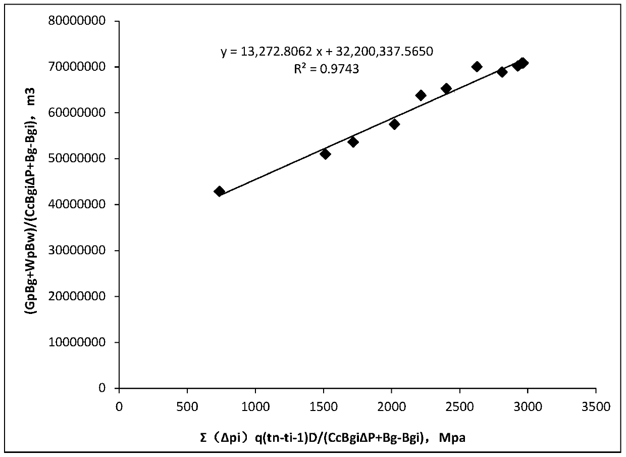
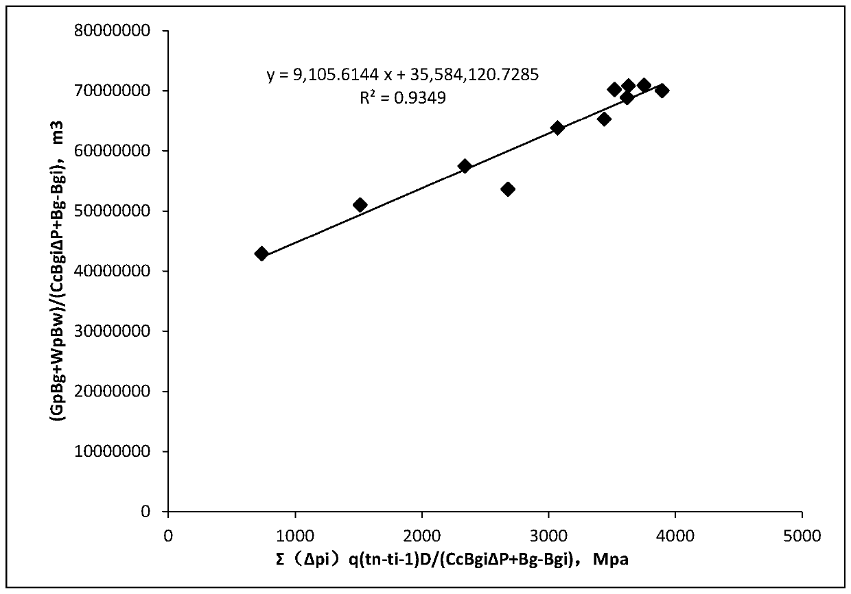
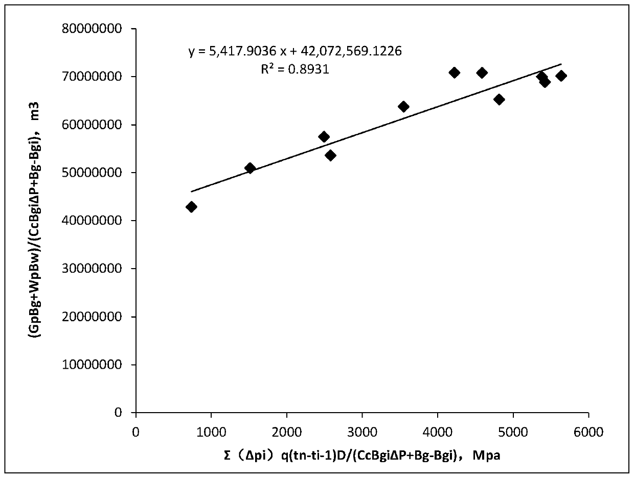
The invention discloses a method for determining water drive gas reservoir parameters under the conditions of rock pore shrinkage and bound water expansion. The method comprises the steps that S1, a material balance equation of a water drive gas reservoir considering the conditions of rock pore shrinkage and bound water expansion is converted into a material balance equation after deformation; S2,a calculation formula of the water influx rate of the gas reservoir to be measured is substituted into the material balance equation after deformation, and a water influx material balance indicationcurve equation is obtained; S3, a water body multiple of the gas reservoir to be measured is set to be 10, and a water influx material balance indication curve is drawn under the water body multiple;S4, the water body multiple of the gas reservoir to be measured is set to be 20, 30, 50 and 150 separately, and the step S3 is repeated to obtain water influx material balance indication curves underdifferent water body multiples; and S5, the water body multiple corresponding to the indication curve with the largest correlation coefficient is the water body multiple of the water drive gas reservoir to be measured, the slope of the curve is a water influx constant of the gas reservoir to be measured, and the intercept of the curve is the dynamic reserve of the gas reservoir to be measured. Themethod is reliable in principle and simple and convenient to operate, and data support and theoretical basis are provided for gas reservoir development.

Description

technical field [0001] The invention belongs to the field of gas reservoir development, and in particular relates to a method for determining the water body multiple, water invasion constant and dynamic reserves of a water drive gas reservoir under the conditions of rock pore shrinkage and bound water expansion. Background technique [0002] my country is rich in natural gas resources, among which water drive gas reservoirs are an important part of my country's gas reservoirs. The edge and bottom water of water drive gas reservoirs constitute the water body of water drive gas reservoirs. To study and accurately determine the size of water bodies in water drive gas reservoirs is of great significance to the production of gas reservoirs, and is very important for the calculation, dynamic analysis and numerical simulation of gas well production in reservoirs. The research on the size of water bodies in water drive gas reservoirs is also conducive to the timely adjustment of pro...

Claims


Application Information

Patent Timeline
IPC IPC(8): E21B43/20E21B49/00E21B43/27
CPCE21B43/20E21B43/26E21B49/00
Inventor 李闽何彦均梁彬赵金洲
Owner SOUTHWEST PETROLEUM UNIV
Learn More