A method and system for recovering arsenic from arsenic-containing flue gas

A technology for recovering arsenic and flue gas, applied in the field of arsenic recovery, can solve the problems of easy paralysis of the system and blockage of equipment by glass arsenic, and achieve the effects of saving expenses, low cost and simple operation

Active Publication Date: 2021-03-26
CENT SOUTH UNIV
View PDF5 Cites 0 Cited by
  • Summary
  • Abstract
  • Description
  • Claims
  • Application Information

AI Technical Summary

Problems solved by technology

[0006] The technical problem to be solved by the present invention is to overcome the deficiencies of the prior art, and provide a method and system for recovering arsenic from arsenic-containing flue gas, so as to solve the problem of glass arsenic blocking equipment caused by arsenic in the natural cooling process, which can replace the arsenic Cold and other large investment systems, and have the advantages of stable and safe operation, avoiding system failure

Method used


Image

  • A method and system for recovering arsenic from arsenic-containing flue gas
  • A method and system for recovering arsenic from arsenic-containing flue gas
  • A method and system for recovering arsenic from arsenic-containing flue gas

Examples


Embodiment 1

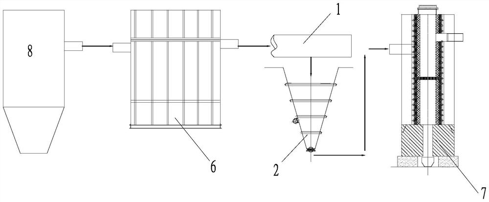
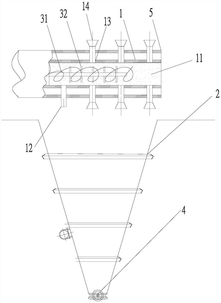
[0072] Arsenic steam by metal filter film: temperature 450 ° C, arsenic 100g / m 3 After entering the trap 1, blow into the cold air, drop the steam temperature to a 40% of the cavity of 5 mm, while blowing a particle size of 5 mm (charcoal powder and calcium oxide, mass ratio 2: 3) accounts for 25% of the quality of the oxide quality. After the natural surface cooler, through the bag is dust, it is 78.9%, carbon 7.84% carbon, 11.64% calcium oxide, and other 1.62% of the smoke, bag, pipe and the tubular and the tandem without oxidation arsenic glass, system normal. The smoke after the collection was reduced in vacuo (temperature 800 ° C, vacuum 20 Pa, and the time was 90min) to give metal arsenic.

Embodiment 2

[0074] Arsenic steam by metal filter film: temperature 450 ° C, arsenic 120g / m 3 After entering the trap 1, blow into the cold air, falling to the flue gas temperature to 350 ° C, and the particle size of 5 mm is blown (charcoal and calcium oxide, mass ratio 2: 4) accounts for 30% of the quality of the oxide quality. After the natural surface cooler, through the bag is dust-containing, 76.2%, carbon 9.12%, carbon oxide, 13.53%, other 1.15% soot, pipe, pipe and refrigerator do not produce oxide glass, the system is normal . Metal arsenic was obtained by vacuum reduction (temperature 900 ° C, vacuum 10 Pa, time length 60min).

Embodiment 3

[0076] Oxidative steam of metal filter film: temperature 450 ° C, arsenic 150g / m 3 After entering the trap 1, blow into the cold wind, falling to the flue gas temperature to 350 ° C, and the blowing agent (reduction pulverized coal and magnesium oxide, mass ratio 2: 3) in the air blowing particle size is 5 mm. 40%, after the natural surface cooler, through the bag is dust-filled, 70.88%, carbon 10.52% carbon, magnesium oxide, and other 2.35% smoke, bag, pipe and the chiller do not produce oxide glass, The system is normal. The smoke after the collection was reduced in vacuo (temperature 850 ° C, vacuum 15 Pa, and 50 min) obtained metal arsenic.


PUM

PropertyMeasurementUnit
melting pointaaaaaaaaaa
particle diameteraaaaaaaaaa
melting pointaaaaaaaaaa

Abstract

The invention discloses a method and system for recovering arsenic from arsenic-containing flue gas. The method comprises the following steps: 1, carrying out dust collection on the arsenic-containingflue gas by a metal film to obtain arsenic-free smoke dust and arsenic oxide steam; 2, mixing the arsenic oxide steam with a solid collecting agent, and obtaining a mixed solid after cooling; and 3,carrying out vacuum reduction on the mixed solid to obtain metal arsenic and reducing slag. The arsenic oxide steam is mixed with the solid collecting agent, the collecting agent is used as a coagulation core for rapidly collecting the liquid arsenic oxide steam and grows in the mixing process, so that the generation of arsenic oxide glass is avoided; and the collected liquid arsenic oxide is condensed into the arsenic oxide solid by natural cooling.

Description

Technical field [0001] The present invention belongs to the field of integrated recovery of non-ferrous metals, and more particularly to a method and system of recovering arsenic from arsenic flue gas. Background technique [0002] 70% of the global arsenic resources have been concentrated in China. Arsenic is mainly derived from arsenic and arsenic ore mining, mineralization, smelting and processing, etc. [0003] Arsenic is a metallite element in elemental geochemistry, and most of the arsenic in nature is symbiitive in the form of sulfide or accompanied by gold, copper, lead, zinc, tin, nickel, cobalt mine, has already been identified. Arsenic minerals have more than 300. Among the 15% copper resources worldwide, a average of 1 ton of arsenic is accompanied by 10% of the tin resources, with an average of 10 tons of arsenic per 1 ton; in 5% gold resources The average arsenic is more than 2,000 tons per 1 ton of gold. During the mining process, 1 ton of non-ferrous metals (gold)...

Claims


Application Information

Patent Timeline
Patent Type & Authority Patents(China)
IPC IPC(8): C22B7/02C22B30/04
CPCC22B7/02C22B30/04Y02P10/20
Inventor 刘维张力攀梁超彭红葵王成军龙森
Owner CENT SOUTH UNIV
Why Eureka
Try Eureka