Bad material removing structure

A technology of inner sleeve and outer sleeve, applied in the field of bad material removal structure, to achieve the effect of convenient use, good removal effect and simple structure

Pending Publication Date: 2019-09-10
ZHONGSHAN ZHANHUI ELECTRONICS EQUIP
View PDF4 Cites 1 Cited by
  • Summary
  • Abstract
  • Description
  • Claims
  • Application Information

AI Technical Summary

Problems solved by technology

but there is a certain degree of difficulty

Method used


Image

  • Bad material removing structure

Examples


Embodiment 1

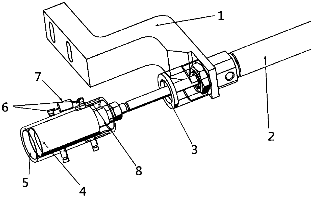
[0017] Example 1: Please refer to figure 1 , a structure for rejecting bad materials, comprising an inner sleeve 4, an outer sleeve 5 slidably connected to each other, and a telescopic cylinder 2 fixedly connected to the mounting base 1, the output end of the telescopic cylinder 2 is fixedly connected to the inner sleeve 4, The telescopic cylinder 2 drives the inner sleeve 4 and the outer sleeve 5 to move forward during the telescopic process. When the outer sleeve 5 contacts the magnetic ring, the telescopic cylinder 2 continues to extend, and the magnetic ring restricts the outer sleeve 5. At this time, the inner sleeve 4 and the outer sleeve 5 move forward. The sleeve 4 moves outward relative to the outer sleeve 5, and the inner sleeve 4 is magnetic, and then attracts with the unqualified magnetic ring. In this case, the relative friction between the outer sleeve 5 and the inner sleeve 4 needs to be small enough , to prevent the outer sleeve 5 from directly pushing the magn...

Embodiment 2

[0023] Embodiment 2: This embodiment is a further improvement of the previous embodiment: the wall of the outer sleeve 5 is provided with an axial hollow hole 8, and the inner sleeve 4 and the outer sleeve 5 are fixedly connected with spring pins. 6. The spring pin 6 on the inner sleeve 4 runs through the hollow hole 8 and the spring pin 6 on the outer sleeve 5 is fixedly connected with a spring 7, and the spring 7 pulls the outer sleeve 5, and after the telescopic cylinder 2 stretches out , the spring 7 directly pulls the outer ends of the inner sleeve 4 and the outer sleeve 5 into a flush state, so as to ensure that the outer sleeve 5 and the inner sleeve 4 release the unqualified magnetic ring at the same time, and prevent the outer sleeve 5 from pushing the magnetic ring to move Case.


PUM


Abstract

The invention discloses a bad material removing structure, and belongs to a removing mechanism. The bad material removing structure comprises an inner sleeve, an outer sleeve and a telescopic cylinder, the inner sleeve and the outer sleeve are connected in a sliding manner, the telescopic cylinder is fixedly connected to a mounting seat, the output end of the telescopic cylinder is fixedly connected with the inner sleeve, the inner sleeve has magnetism, the outer sleeve does not have magnetism, and a limiting block used for limiting axial motion of the outer sleeve during contraction is fixedly connected to the mounting seat. Compared with the prior art, the bad material removing structure has the beneficial effects that the structure is simple, use is facilitated, a T1T2 magnetic ring canbe effectively removed in use, and the inner sleeve and the magnetic ring are attracted by stretching of the telescopic cylinder, then the telescopic cylinder retracts back, the position of the outersleeve is limited through the limiting block, the outer sleeve jacks out the magnetic ring, contact between the magnetic ring and the inner sleeve is ended, then the magnetic ring and the inner sleeve fall, and the removing effect is good.

Description

technical field [0001] The invention relates to a rejecting mechanism, in particular to a bad material rejecting structure. Background technique [0002] The magnetic ring is an anti-interference component commonly used in electronic circuits. It has a good suppression effect on high-frequency noise and is generally made of ferrite materials. The magnetic ring has different impedance characteristics at different frequencies. Generally, the impedance is very small at low frequencies. When the signal frequency increases, the impedance of the magnetic ring increases sharply. Everyone knows that the higher the frequency of the signal, the easier it is to radiate out, and the general signal lines are not shielded, so these signal lines become good antennas, receiving various messy high-frequency signals in the surrounding environment, And these signals are superimposed on the originally transmitted signal, and even change the original useful signal transmitted. Then under the a...

Claims


Application Information

Patent Timeline
Patent Type & Authority Applications(China)
IPC IPC(8): B07C5/36
CPCB07C5/362
Inventor 陈巨亮文先庚严有朋
Owner ZHONGSHAN ZHANHUI ELECTRONICS EQUIP
Why Eureka
Try Eureka