
Panoramic image shooting method

A panorama image and shooting method technology, which is applied in image communication, color TV parts, TV system parts, etc., can solve the problems of image splicing and viewing discomfort, etc., and achieves lower hardware costs and lighter weight. , the effect of system structure simplification

Inactive Publication Date: 2019-09-06
NANJING HONGZHONG ELECTRONICS TECH
View PDF6 Cites 6 Cited by
  • Summary
  • Abstract
  • Description
  • Claims
  • Application Information

AI Technical Summary

Problems solved by technology

However, due to the existence of parallax, there will be differences in the images in the overlapping area, resulting in misalignment of the splicing, and the abnormal splicing will bring discomfort to the viewing

Method used


Image

  • Panoramic image shooting method
  • Panoramic image shooting method
  • Panoramic image shooting method

Examples


Embodiment

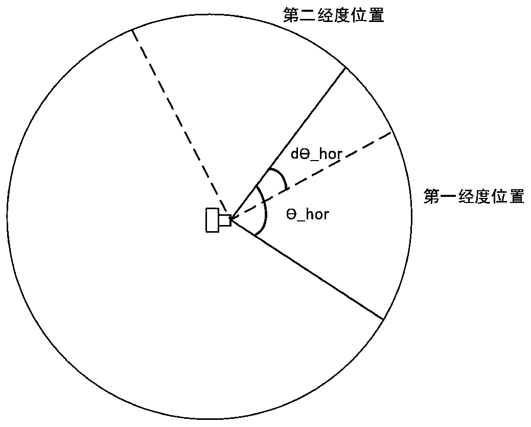
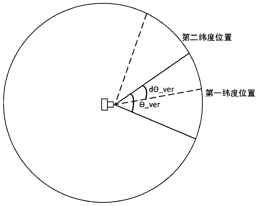
[0028] Embodiment: a kind of shooting method of panoramic image, comprises the steps:

[0029] (1) Determine the node of the lens module and connect the lens module with a rotating mechanism to ensure that the distance between the lens node and the rotation center of the rotating mechanism is less than or equal to 3cm. If conditions permit, the best choice It is to coincide the lens node of the lens module with the rotation center of the rotation mechanism.

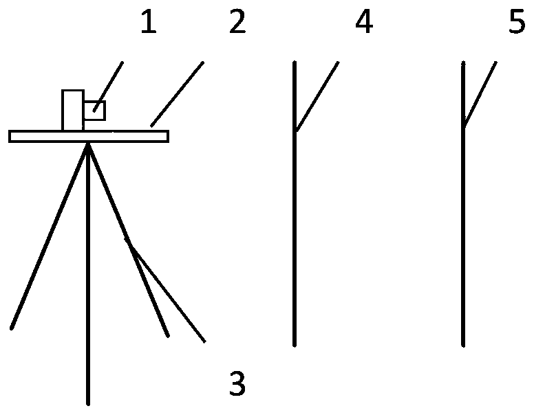
[0030] The method of determining the node of the lens module is as follows:

[0031] Slidingly install the lens module 1 on the guide rod 2, and move the lens module 1 forward and backward along the guide rod 2. The optical axis of the lens of the lens module 1 is parallel to the guide rod 2, and fix the guide rod 2 on the tripod 3 , adjust the guide rod 2 to the horizontal position; place two vertically placed reference objects in front of the lens module 1, respectively called the first reference object 4 and the secon...


PUM


Abstract

The invention discloses a panoramic image shooting method, which comprises the following steps of: connecting a lens module with a rotating mechanism to ensure that the distance between a lens node and the rotating center of the rotating mechanism is less than or equal to 3cm; setting parameters of the rotation angle and the number of rotation times of the rotation mechanism; enabling the rotatingmechanism to rotate according to set parameters to drive the lens module to rotate to different angle positions, and enabling a lens of the lens module to collect an area image of the current view field until all the area images needed by splicing of the panoramic images are collected; enabling the image synthesizing apparatus to synthesize the plurality of area images into a panoramic image. Thedistance between the lens node and the rotating center of the rotating mechanism is smaller than or equal to 3 cm, the image parallax can be effectively reduced, the imaging quality of a final panoramic image is improved, and meanwhile the requirements and the cost for software and algorithms are reduced.

Description

technical field [0001] The invention relates to the technical field of photography, in particular to the technical field of panoramic image shooting and generation. Background technique [0002] Panoramas express as much of the surrounding environment as possible through wide-angle means of expression and forms such as paintings, photos, videos, and 3D models. 360 panorama, that is, by capturing the image information of the entire scene with a professional camera or using a modeling software to render the picture, use the software to stitch the pictures, and play it with a special player, that is, turn the plane photo or computer modeling picture into a 360-degree Panorama, used for virtual reality viewing, simulates a two-dimensional plan into a real three-dimensional space and presents it to viewers. Panoramic images record information in 360-degree space. When displaying panoramic images, you can drag the image screen to browse. The 360-degree full recording feature and ...

Claims


Application Information

Patent Timeline
Patent Type & Authority Applications(China)
IPC IPC(8): H04N5/225H04N5/232
CPCH04N23/50H04N23/55H04N23/54H04N23/66H04N23/698
Inventor 沈峘张佩泽程百顺王汉全
Owner NANJING HONGZHONG ELECTRONICS TECH
Learn More