
Wireless charging base and wireless charging base control method

A wireless charging and waiting-to-charge technology, applied in battery circuit devices, current collectors, electric vehicles, etc., can solve the problems of stable operation of the system, the influence of charging speed, the decrease of electromagnetic energy transmission efficiency, and the failure of triggering.

Pending Publication Date: 2019-09-06
GUANGDONG OPPO MOBILE TELECOMM CORP LTD
View PDF0 Cites 4 Cited by
  • Summary
  • Abstract
  • Description
  • Claims
  • Application Information

AI Technical Summary

Problems solved by technology

[0004] However, when the user places the device to be charged on the wireless charging base, it often happens that the placement position of the structural coil of the device to be charged deviates from the generating coil of the wireless charging base.
After this happens, the efficiency of electromagnetic energy transmission decreases due to the decrease in the coupling degree between the transmitting coil and the receiving coil, and the transmitting coil needs to provide more energy to maintain the charging power of the receiving coil
Due to the offset of the device to be charged, the transmitting coil needs to emit more energy, which causes the wireless charging base to heat up, which affects the stable operation of the system and the charging speed
When the device to be charged is placed too far away, it will cause the charging failure of the wireless charging base or the failure of the trigger, resulting in the inability to charge, etc.

Method used


Image

  • Wireless charging base and wireless charging base control method
  • Wireless charging base and wireless charging base control method
  • Wireless charging base and wireless charging base control method

Examples


Embodiment Construction

[0025] Although the present invention can easily be embodied in different forms of embodiments, only some of the specific embodiments are shown in the drawings and described in detail in this specification. At the same time, it is understood that this specification should be regarded as the present specification. Exemplary descriptions of the disclosed principles are not intended to limit the present invention to what is described herein.

[0026] Therefore, a feature pointed out in this specification will be used to illustrate one of the features of an embodiment of the present disclosure, rather than implying that each embodiment of the present invention must have the described feature. In addition, it should be noted that this specification describes many features. Although certain features can be combined to illustrate possible system designs, these features can also be used in other unspecified combinations. Thus, unless otherwise stated, the illustrated combinations are no...


PUM


Abstract

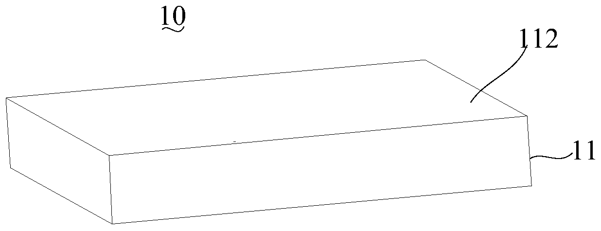
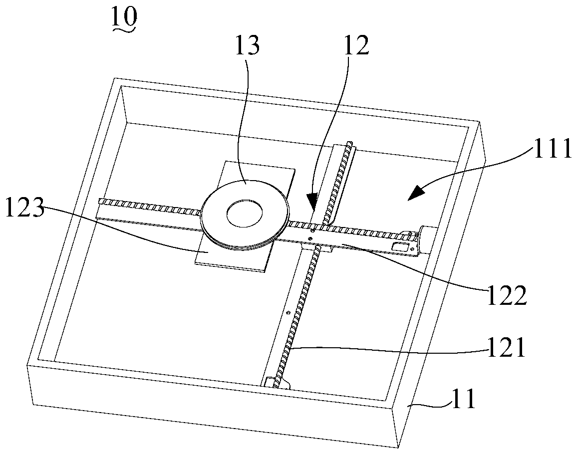
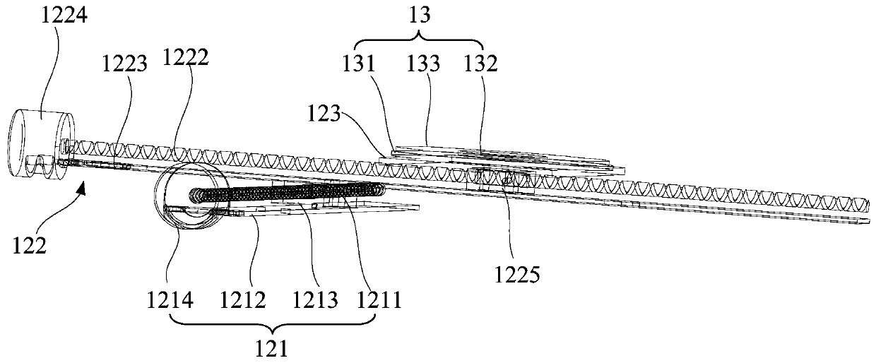
The invention provides a wireless charging base and a wireless charging base control method. The wireless charging base comprises a base body, wherein a charging plane is used for containing a deviceto be charged is arranged in the base body. A charging module is arranged in the base body. A movement mechanism is arranged in the base body. The charging module is movably arranged on the movement mechanism, and the movement mechanism drives the charging module to move. The movement mechanism moves under the charging plane to enable the charging module to traverse the whole charging plane underthe charging plane, so that the position coordinates of the to-be-charged device is obtained according to the coupling degree of the charging module and each position of the to-be-charged device on the charging plane, the target position coordinate of the charging module is determined according to the position coordinate of the to-be-charged device; and the movement mechanism enables the chargingmodule to move to the target position coordinate. The charging module of the wireless charging base can be mutually aligned with a receiving coil of the device to be charged, so that the charging efficiency of the device to be charged by the wireless charging base is ensured.

Description

Technical field [0001] The invention relates to the field of wireless charging, in particular to a wireless charging base and a wireless charging base control method. Background technique [0002] Wireless charging technology is derived from wireless power transmission technology, which can be divided into low-power wireless charging and high-power wireless charging. Since the charger and the device to be charged use a magnetic field to transmit energy, there is no wire connection between the two. [0003] At present, most of the wireless chargers on the market are wireless charging bases, which are equipped with a transmitting coil, and the device to be charged is equipped with a receiving coil. When the device to be charged is wirelessly charged, the positions of the transmitter coil of the wireless charging base and the receiver coil of the device to be charged are aligned with each other to ensure smooth charging. [0004] However, when the user places the device to be charged ...

Claims


Application Information

Patent Timeline
IPC IPC(8): H02J7/00H02J50/90H02J50/10
CPCH02J7/025H02J50/90H02J50/10
Inventor 江森龙万世铭张加亮张俊
Owner GUANGDONG OPPO MOBILE TELECOMM CORP LTD
Learn More