
Steel-board bending device for refrigerator door

A technology for bending device and refrigerator door, which is applied in the direction of household refrigeration device, application, household appliances, etc., can solve the problem of difficulty in changing the bending angle of door steel plate

Inactive Publication Date: 2003-02-26
SAMSUNG ELECTRONICS CO LTD
View PDF0 Cites 2 Cited by
  • Summary
  • Abstract
  • Description
  • Claims
  • Application Information

AI Technical Summary

Problems solved by technology

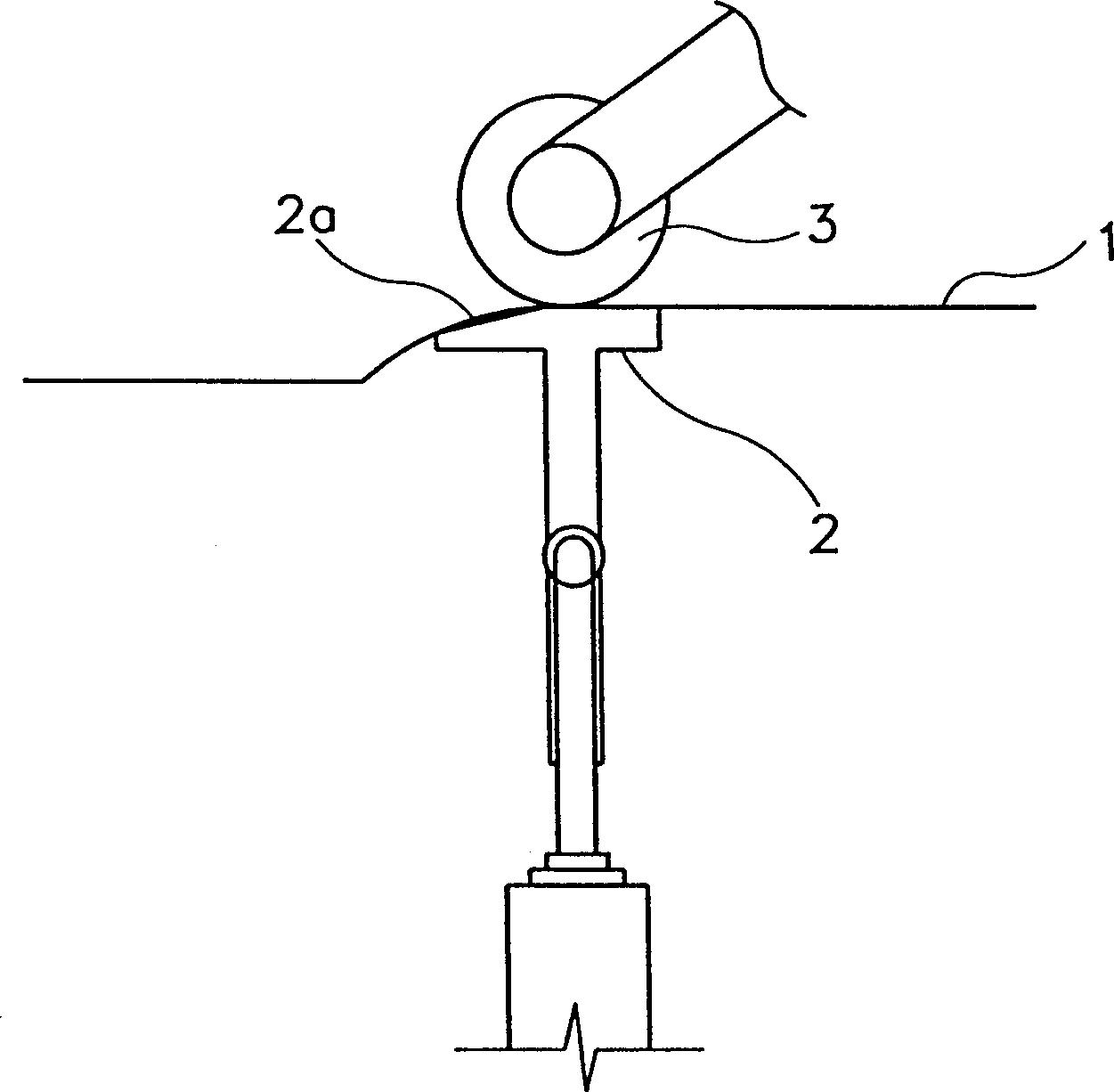
[0004] However, there is a problem with this conventional bending device that it is difficult to change the bending angle of the door steel plate because the bracket must be replaced if the bending angle is to be changed.

Method used


Image

  • Steel-board bending device for refrigerator door
  • Steel-board bending device for refrigerator door
  • Steel-board bending device for refrigerator door

Examples


Embodiment Construction

[0013] The present invention will be further described below according to the preferred embodiments shown in the accompanying drawings.

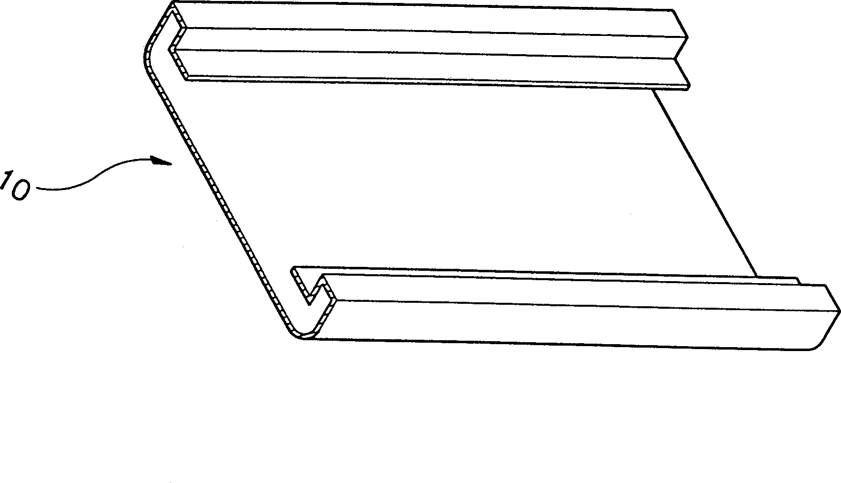
[0014] figure 1 Shown is a steel plate for a bilaterally bent refrigerator door that is completed using the bending device of the present invention. Such as figure 1 As shown, the door is composed of a steel plate 10 with both sides bent, an inner shell (not shown) with both sides connected to the bent portion of the steel plate 10, and a heat insulating material (not shown) filled between the steel plate and the inner shell .

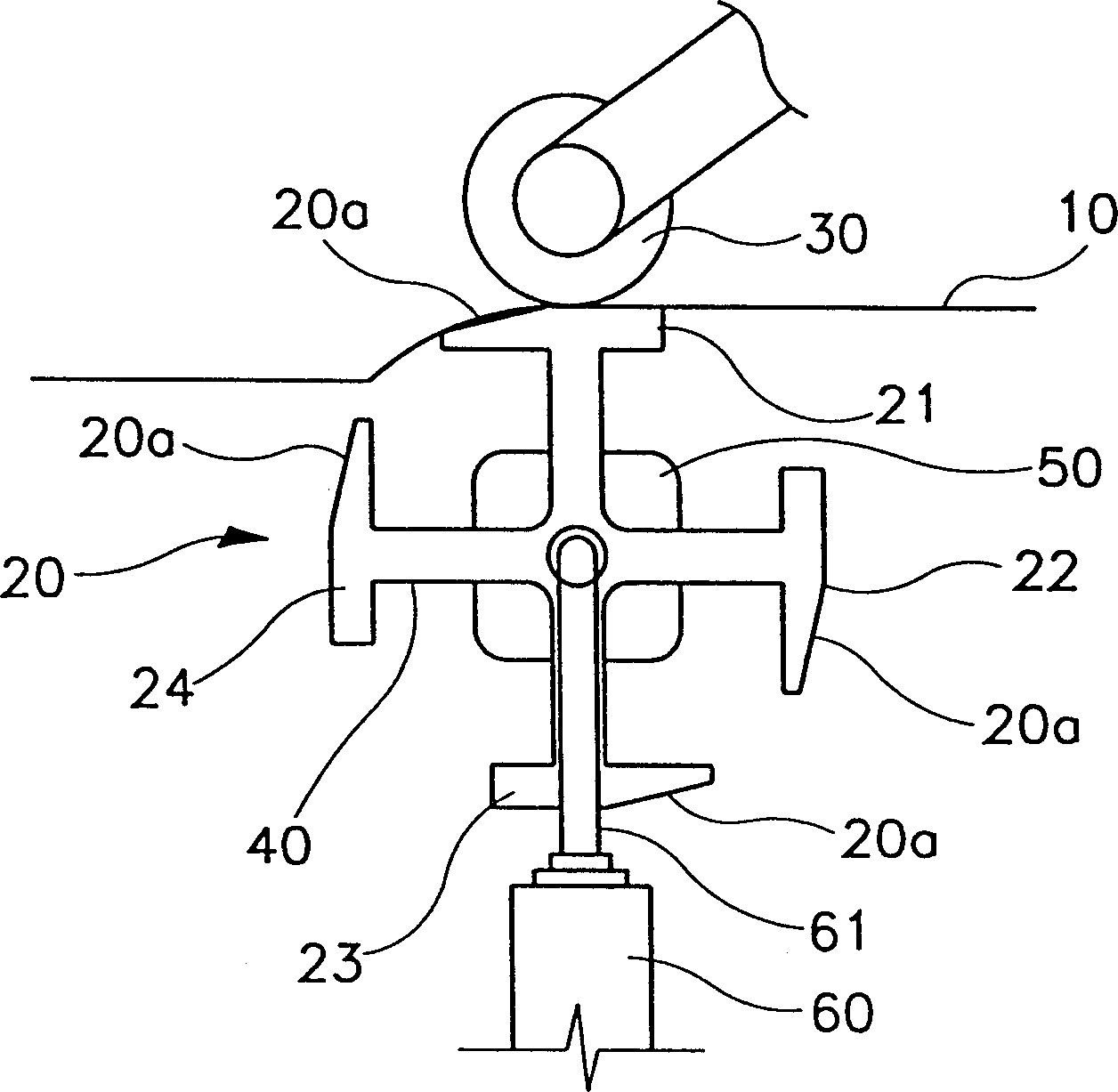
[0015] Both sides of the steel plate 10 are bent into obtuse angles, and then bent into three 90° angles. The present invention relates to a device for bending both sides of a steel plate 10 of a door into an obtuse angle. figure 2 shows the bending device of the present invention, as figure 2 As shown, the door steel plate bending device includes: four metal parts 21, 22, 23, 24 with slopes with different i...


PUM


Abstract

An iron sheet bending device for a refrigerator door is provided with a roll and dies mutually and closely arranged so that the iron sheet positioned among them is bent. In this case, plural dies are provided with, inclined surfaces inclined with mutually different angles are formed to side surfaces of respective dies opposing to the roll, an approaching means selectively approaching plural dies to the roll is provided with, and the angle bent with the roll and dies is selectively regulated.

Description

technical field [0001] The present invention relates to a steel plate bending device for a refrigerator door, more specifically, to a steel plate for a refrigerator door that can easily change the bending angle by selectively fixing several metal pieces with different inclination angles to rollers bending device. Background technique [0002] Common refrigerator doors are made of steel plates, inner shells and insulating materials filled between them. Both sides of the steel plate are bent inward, and the inner shell is connected with the edge of the steel plate. [0003] image 3 A conventional bending device for bending both sides of a steel plate is shown. Such as image 3 As shown, the door panel 1 is placed between the bracket 2 and the roller 3, pressed and bent, and the slope 2a inclined at a predetermined angle is on the side of the bracket 2 facing the roller 3, so that the steel plate 1 of the door is bent along the slope 2a . As the rol...

Claims


Application Information

Patent Timeline
Patent Type & Authority Patents(China)
IPC IPC(8): B21D19/04B21D5/00B21D5/08F25D23/02
CPCB21D5/08B21D37/06B21D37/10
Inventor 林在勋黄南洙
Owner SAMSUNG ELECTRONICS CO LTD
Learn More