
Energy-saving type high-speed laminating composite unit

An energy-saving, coating technology, applied in the field of coating compounding, can solve the problems of increased raw material costs, poor cutting accuracy, heat loss, etc., and achieve the effects of improving cutting effects, improving product quality, and saving processing costs

Active Publication Date: 2019-09-06
浙江康骏机械有限公司
View PDF17 Cites 4 Cited by
  • Summary
  • Abstract
  • Description
  • Claims
  • Application Information

AI Technical Summary

Problems solved by technology

[0003] When the existing laminating compound machine is in use, the extruded part of the laminating machine is exposed to the air, and the heat loss is relatively serious, which requires continuous heating, resulting in waste of electric energy and increased production costs of the equipment. , the rubber roller hydraulically presses the coating on the raw material, and part of the coating liquid cannot be completely attached, resulting in the accumulation of waste, affecting the coating of the raw material, and finally causing the thickness of the coating to vary, and the product quality is greatly affected. Furthermore, the existing Most of the edge trimming knives after lamination are directly fixed by the cutting knife and cut by the propulsive force of the roller. The cutting accuracy is poor, and it is easy to appear inclined cutting during cutting, resulting in scrapped products, increasing raw material costs, and reducing equipment production. Efficiency, for this reason, we propose an energy-saving high-speed laminating compound unit

Method used


Image

  • Energy-saving type high-speed laminating composite unit
  • Energy-saving type high-speed laminating composite unit
  • Energy-saving type high-speed laminating composite unit

Examples


Embodiment Construction

[0026] The following will clearly and completely describe the technical solutions in the embodiments of the present invention with reference to the accompanying drawings in the embodiments of the present invention. Obviously, the described embodiments are only some, not all, embodiments of the present invention. Based on the embodiments of the present invention, all other embodiments obtained by persons of ordinary skill in the art without making creative efforts belong to the protection scope of the present invention.

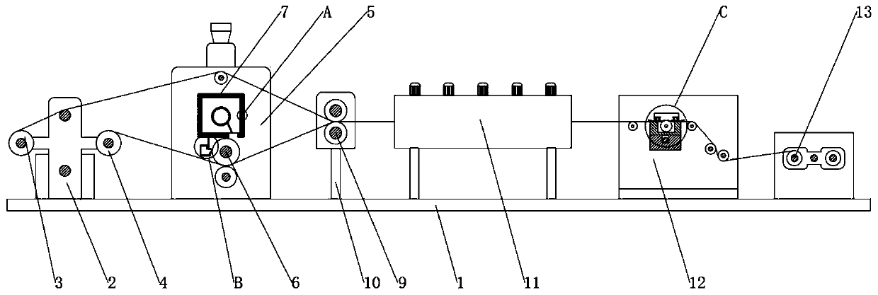
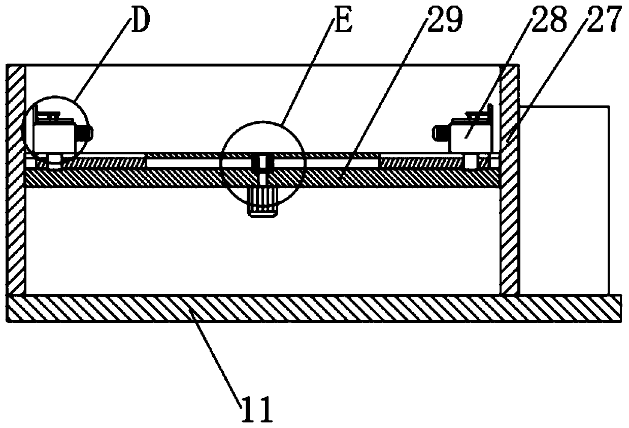
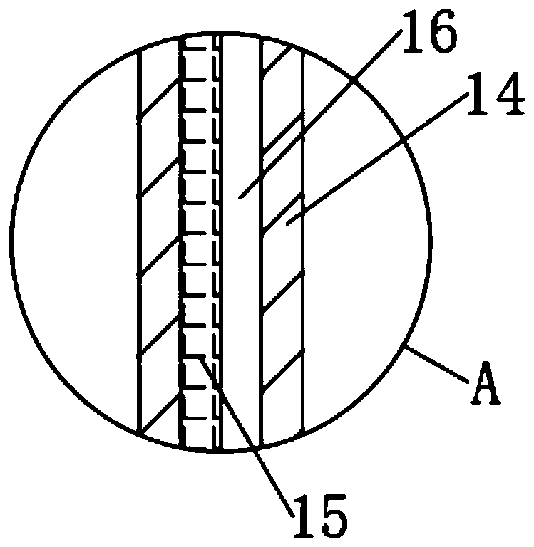
[0027] see Figure 1-9 , the present invention provides a technical solution: an energy-saving high-speed laminating compound unit, including a base plate 1, a feeding plate 2, a first feeding roller 3, a second feeding roller 4, a laminating device 5, rubber rollers 6, Heat preservation device 7, auxiliary device 8, composite roller 9, support frame 10, drying equipment 11, cutter adjustment device 12 and material receiving equipment 13, the top of one side o...


PUM


Abstract

The invention discloses an energy-saving type high-speed laminating composite unit. The energy-saving type high-speed laminating composite unit comprises a base plate, feeding plates, a first feedingroller, a second feeding roller, a laminating device, a rubber roller, a heat preservation device, an auxiliary device, a composite roller, a supporting frame, a drying device, a cutter adjusting device and a collecting device, wherein the feeding plates are fixed on the top of one side of the base plate; the first feeding roller is arranged between the feeding plates and the first feeding rolleris rotationally connected with the feeding plates; the second feeding roller is arranged between the feeding plates and the second feeding roller is rotationally connected with the feeding plates; andthe laminating device is arranged on one side of the feeding plate. According to the energy-saving type high-speed laminating composite unit, the heat preservation device is additionally arranged onan original laminating compound machine, so that the temperature of the laminating machine is ensured, the electric energy consumption of heating is reduced, and the processing cost is reduced; and the adjusting device is additionally arranged at the laminating position, waste on the surface of the rubber roller is removed, the uniformity of laminating is ensured, the adhesion of compounding is ensured, and the product quality is improved.

Description

technical field [0001] The invention relates to the technical field of laminating and compounding, in particular to an energy-saving high-speed laminating and compounding unit. Background technique [0002] Laminating machine is also known as extrusion compound machine, casting machine, extrusion casting machine, casting compound machine, film coating machine, plastic coating machine, coating compound machine (not accurate, actually refers to hot melt adhesive blade coating machine ), is a kind of extrusion molding machine, which has the advantages of high automation, easy operation, high production speed, uniform coating thickness, high adhesion fastness, smooth coiling, environmental protection and pollution-free, saving labor and raw material costs, etc. It has matured in Europe and the United States, and gradually began to be used in China. It is an inevitable trend to replace dry lamination and hot melt adhesive coating lamination. [0003] When the existing laminating...

Claims


Application Information

Patent Timeline
Patent Type & Authority Applications(China)
IPC IPC(8): B05C1/08B05C11/10B26D1/15B26D7/02B26D7/26
CPCB05C1/0817B05C11/1039B05C11/1042B26D1/151B26D7/025B26D7/2628
Inventor 胡一帆黄银锋陈春雷潘银威
Owner 浙江康骏机械有限公司
Learn More