


Quick Research
Generate reliable direction feasibility study reports for your R&D in just a few steps.

Technical Q&A
Discover and master advanced knowledge NOW. Basics, ideas, possibilities, all at once.

Find Solutions
As an expert in R&D theories, this can generate solutions to your technical problems instantly.

Evaluate Feasibility
Analyze your overall solution with one click, know your potential R&D risks in advance.

Monitor Landscape
Get weekly tech updates, stay abreast of the latest tech innovations and key insights.
Continuous casting device for thin slabs
A technology for slabs and metal slabs, applied in the field of continuous casting devices, can solve problems such as high component maintenance costs, high structure and maintenance costs, and achieve the effects of simplifying functions, reducing quantities, and reducing complexity
- Summary
- Abstract
- Description
- Claims
- Application Information
AI Technical Summary
Problems solved by technology
Method used
Image


Examples
Embodiment Construction
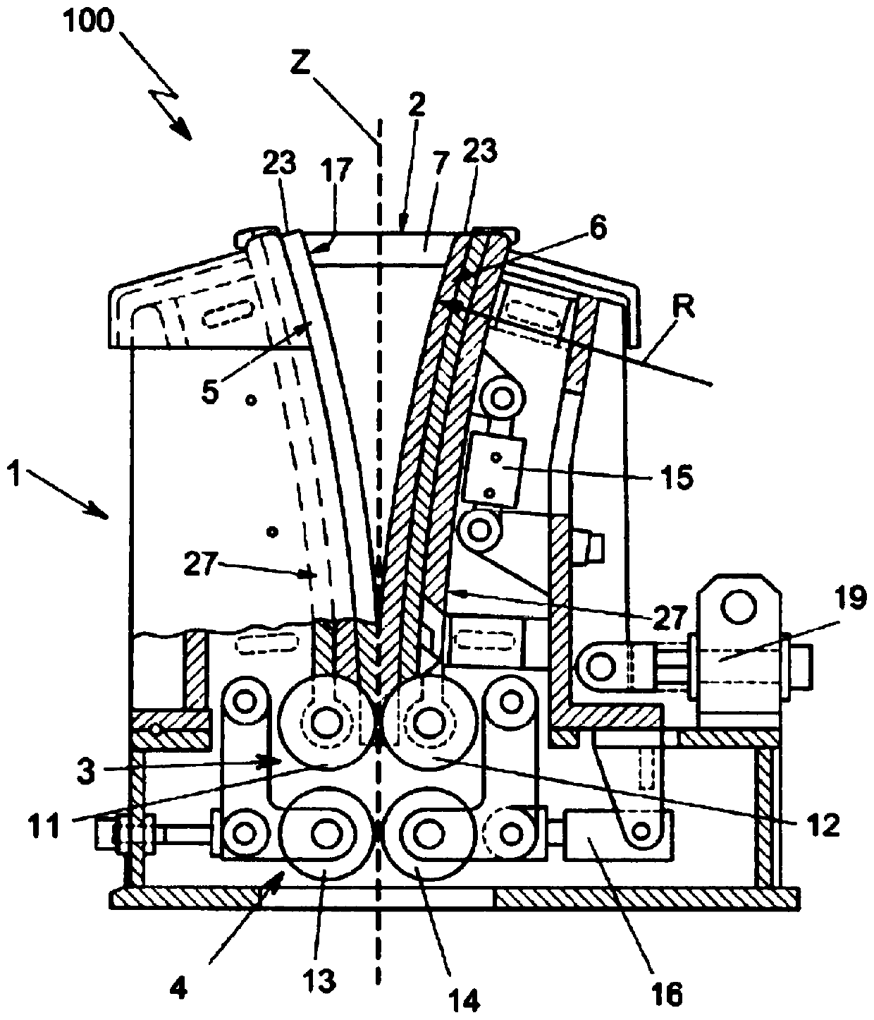
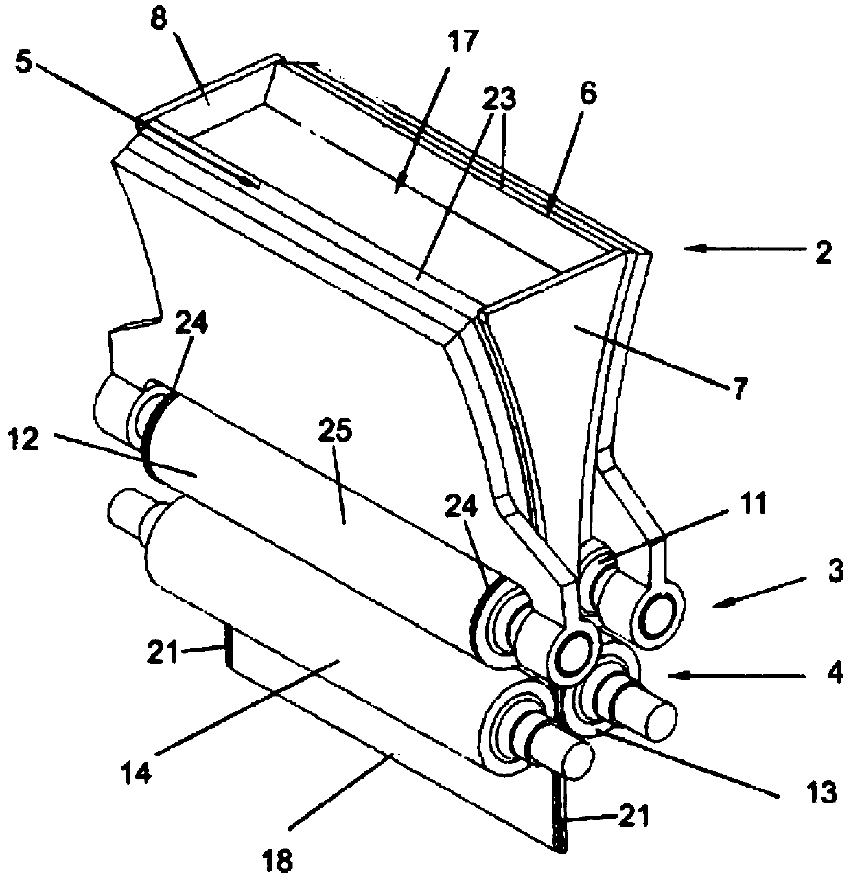
[0036] With reference to the drawings, a thin slab casting apparatus generally indicated by reference numeral 100 comprises in a preferred but not exclusive configuration a mold 1 or casting apparatus provided with a crystallizer 2 configured To make the liquid metal introduced into the crystallizer 2 solidify.
[0037] The crystallizer 2 comprises two first walls 5, 6 having the configuration of plates facing each other and two second walls 7, 8 also having The plates facing each other and connected to the first walls 5, 6 are configured to together define a recess 17 containing the cast liquid metal.
[0038] The first walls 5, 6 substantially define the planar surface of the slab, while the second walls 7, 8 substantially define the thickness of the slab.
[0039] The width of the first walls 5 , 6 substantially corresponds to the width of the slab 18 , being much greater than the width of the second walls 7 , 8 . Merely by way of example, the width of the first wall 5 , ...
PUM
 Abstract
Description
Claims
Application Information
 - R&D Engineer
- R&D Manager
- IP Professional
- Industry Leading Data Capabilities
- Powerful AI technology
- Patent DNA Extraction
Browse by: Latest US Patents, China's latest patents, Technical Efficacy Thesaurus, Application Domain, Technology Topic, Popular Technical Reports.
© 2024 PatSnap. All rights reserved.Legal|Privacy policy|Modern Slavery Act Transparency Statement|Sitemap|About US| Contact US: help@patsnap.com