
Brake locking device and method of use of beam pumping unit

A beam pumping unit and lock-stop technology, which is applied in earthwork drilling, mechanical equipment, wellbore/well components, etc., can solve the problems of operator safety hazards, unstable use, brake failure, etc., and achieve the braking effect Good, the overall structure is closely connected, and the brake lock effect is good

Inactive Publication Date: 2020-09-04
宋晶鑫 +2
View PDF4 Cites 0 Cited by
  • Summary
  • Abstract
  • Description
  • Claims
  • Application Information

AI Technical Summary

Problems solved by technology

[0002] The beam pumping unit is driven by the motor to drive the reducer, and the reducer drives the crank to work. When the beam pumping unit needs to stop, it is braked by the friction brake device on the reducer, but the friction brake device When the friction pair is used for a long time, it will wear out, and sometimes the brakes will fail. If the brakes cannot be used, it will bring danger to the safety of the operator, and there are unstable factors in use.

Method used


Image

  • Brake locking device and method of use of beam pumping unit
  • Brake locking device and method of use of beam pumping unit
  • Brake locking device and method of use of beam pumping unit

Examples


Embodiment 1

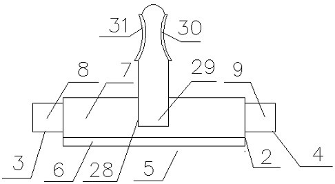
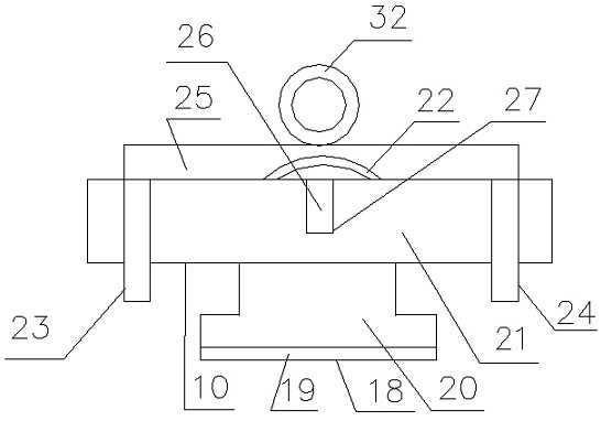
[0020] A beam pumping unit brake locking device, which consists of: a reducer, the reducer has an outer shell 1, the outer shell has a slanted inlaid groove 2, a slanted inlaid groove of the described One side is connected to the upper chute 3, and the other side is connected to the lower chute 4. The bottom of the first half of the inclined inlaid groove is connected to the groove 5. The height of the groove is lower than that of the inclined inlaid groove. The groove is bonded with a flat magnetic Plate 6, the second half of the inclined mosaic groove is equipped with a sliding magnetic plate 7, the flat magnetic plate does not affect the sliding of the sliding magnetic plate, and can play the role of suction and fixing, the sliding magnetic plate is connected to the upper plug Plate 8, the upper board is inserted into the upper chute and slides, the upper board ensures that the sliding magnetic board will not break away from the inclined inlay groove when it is loaded and sl...

Embodiment 2

[0022] In the brake locking device of a beam pumping unit described in Embodiment 1, the output shaft is connected to the crank 15 of the beam pumping unit, and the crank rotates around the output shaft. The inner lower part of the crank is provided with a flat inlaid groove 16, and the flat inlaid groove is welded with a brake iron plate 17. The brake iron plate does not protrude from the surface of the crank, and the brake iron plate does not protrude from the surface of the crank. Affect the normal use of the crank. When braking is required, the brake iron plate can fix (brake) the crank to ensure that the crank does not continue to rotate. When braking is required, the sliding magnetic plate is pushed forward and inserted into the outer shell Between the crank, the brake iron plate is attracted and fixed, and the sliding magnetic plate absorbs the brake iron plate to play the role of a heavy brake.

Embodiment 3

[0024] A brake and lock device for a beam pumping unit described in Embodiment 1, the bottom of the brake groove is connected to the inverted T-shaped chute 18, and the bottom of the inverted T-shaped chute is bonded to the bottom magnetic plate 19 , the inverted T-shaped iron slider 20 is housed in the inverted T-shaped chute, the top of the inverted T-shaped iron slider is connected to the brake skateboard 21, and the inverted T-shaped iron slider can be placed in the inverted T-shaped chute Sliding, when the brake is not needed, the brake skateboard is located in the second half of the inverted T-shaped chute, without hindering the normal operation of the crank. The brake socket further functions as a brake to ensure that the crank is not in operation (action). The tail end of the brake skateboard is fixedly connected to the handle 22, and the handle is located at the tail end of the brake skateboard, so that it does not affect the crank when not braking. In normal use, the...


PUM


Abstract

The invention discloses a beam-pumping unit brake locking device and a using method. The device comprises a speed reducer and a shell, wherein the speed reducer is provided with a shell body, an inclined embedded groove is formed in the shell body, the inclined embedded groove is connected with an upper sliding groove and a lower sliding groove, the bottom of the front half part of the inclined embedded groove is connected with a groove, the groove is adhesively connected with a flat magnetic plate, a sliding magnetic plate is installed at the back half part of the inclined embedded groove, anupper insertion plate is connected with the sliding magnetic plate, the upper insertion plate is inserted into the upper sliding groove and can slide, the sliding magnetic plate is connected with a lower insertion plate, and the lower insertion plate is inserted into the lower sliding groove and can slide; the shell body is provided with a brake groove, a triangular brake plug-in is arranged inside the brake groove, the speed reducer is provided with an output shaft, a brake disc is fixedly connected to the outer side of the output shaft, a set of triangular brake sockets are formed around the circumference of the brake disc, and the triangular brake plug-in is inserted into the triangular brake sockets to fix the output shaft. The locking device is used for beam-pumping unit braking.

Description

Technical field: [0001] The invention relates to a brake locking device and a using method of a beam pumping unit. Background technique: [0002] The beam pumping unit is driven by the motor to drive the reducer, and the reducer drives the crank to work. When the beam pumping unit needs to stop, it is braked by the friction brake device on the reducer, but the friction brake device When the friction pair is used for a long time, it will wear out, and sometimes the brake will fail. If the brake cannot be used, it will bring danger to the safety of the operator, and there will be unstable factors in use. Invention content: [0003] The object of the present invention is to provide a brake locking device for a beam pumping unit that can be externally installed, has a good braking effect and is safe to use, and a method for using it. [0004] Above-mentioned purpose realizes by following technical scheme: [0005] A beam-pumping unit brake locking device, which consists of: ...

Claims


Application Information

Patent Timeline
Patent Type & Authority Patents(China)
IPC IPC(8): F16D63/00E21B43/12
CPCE21B43/127F16D63/006
Inventor 宋晶鑫刘洪俊庄立君贾瑞成蒋玉林王立臣段庆斌李雪梅唐海燕姜树生王晓伟郑晓蕾梁丽刘翠霞郭英健
Owner 宋晶鑫
Learn More