
Electronic equipment

A technology of electronic equipment and transparent cover, which is applied to branch office equipment, TVs, color TVs, etc., can solve the problems of small screen ratio, increased cost, and increased structural complexity, so as to reduce the size of black borders and increase screen occupation Ratio, the effect of reducing the thickness

Pending Publication Date: 2019-08-30
GUANGDONG OPPO MOBILE TELECOMM CORP LTD
View PDF0 Cites 4 Cited by
  • Summary
  • Abstract
  • Description
  • Claims
  • Application Information

AI Technical Summary

Problems solved by technology

[0003] Among them, structures such as notch screens and water drop screens have relatively large damage to the screen, and the cost of the screen will relatively increase; moreover, it visually destroys the beauty of the integrated screen, which some consumers cannot accept.
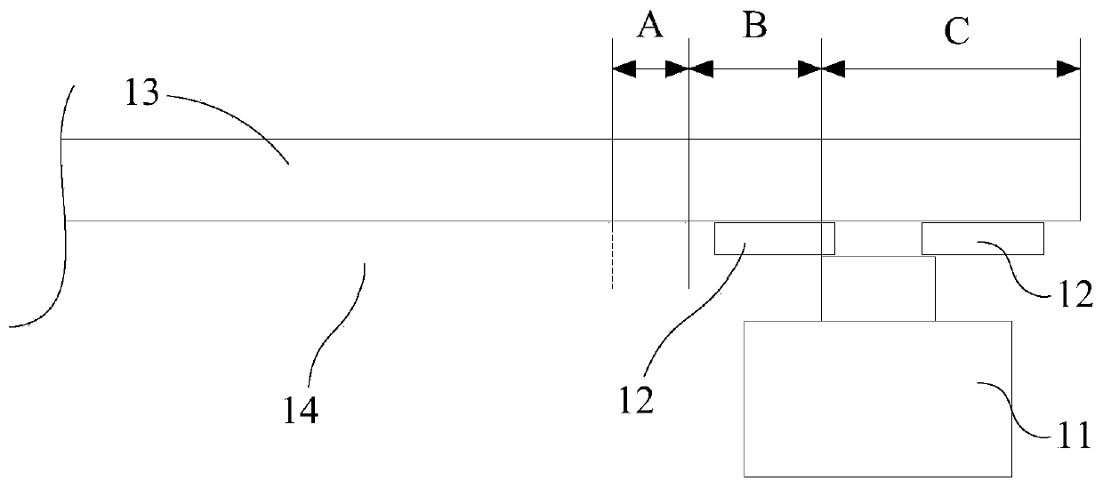
Other full-screen solutions (such as a telescopic camera, a dual-screen solution with only the rear being canceled, and a flip camera solution) have higher requirements for the whole machine, increase the structural complexity, increase the difficulty of stacking and detailed design of the whole machine, and increase the cost. will increase accordingly
Although the design scheme of narrow bezel and hole-digging screen is used in many electronic devices, it can make the whole machine more integrated, but due to the size of the front camera and the different assembly methods, the screen-to-body ratio will be lower than other solutions. Small, has been difficult to break through

Method used


Image

  • Electronic equipment
  • Electronic equipment
  • Electronic equipment

Examples


Embodiment Construction

[0029] The application will be described in further detail below in conjunction with the accompanying drawings and embodiments. In particular, the following examples are only used to illustrate the present application, but not to limit the scope of the present application. Likewise, the following embodiments are only some of the embodiments of the present application but not all of them, and all other embodiments obtained by those skilled in the art without creative efforts fall within the protection scope of the present application.

[0030] Reference in this application to an "embodiment" means that a particular feature, structure, or characteristic described in connection with the embodiment can be included in at least one embodiment of the present application. The occurrences of this phrase in various places in the specification are not necessarily all referring to the same embodiment, nor are separate or alternative embodiments mutually exclusive of other embodiments. It...


PUM


Abstract

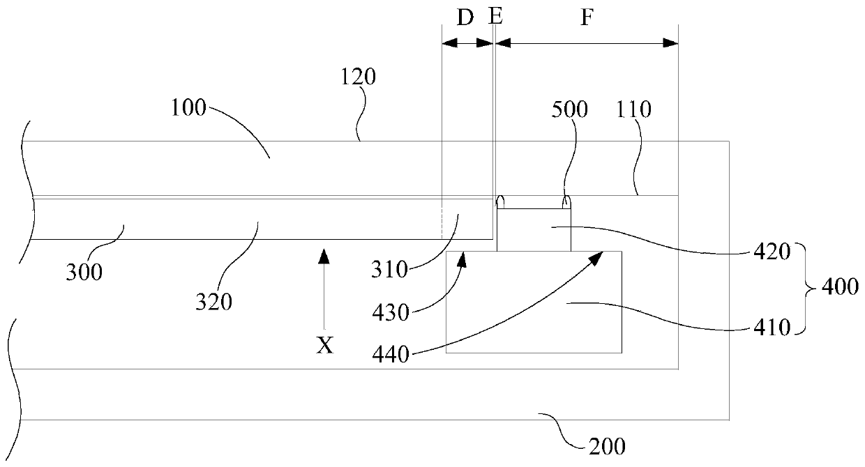
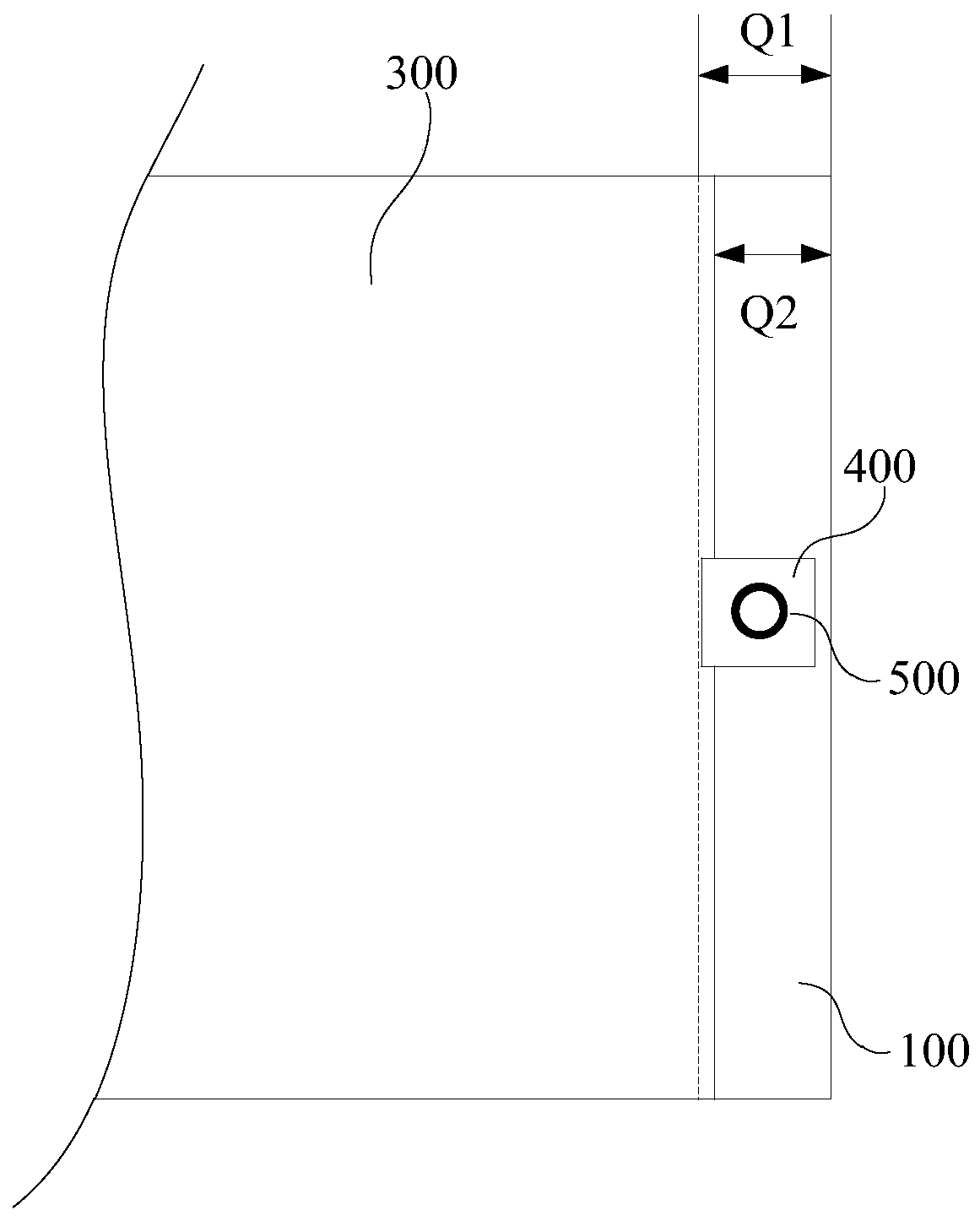
The invention provides electronic equipment which comprises a transparent cover plate, a shell, a display screen, a camera module and a shading structure, and the shell and the transparent cover plateare connected and jointly form a containing space in a surrounding mode; the display screen is arranged in the accommodating space; the camera module is arranged in the accommodating space and is adjacent to the display screen; the camera module comprises a fixing base and a lens, a first extending face is arranged on the side, connected with the lens, of the fixing base, and the display screen abuts against the first extending face and the side face of the lens. The light shielding structure is arranged between the camera module and the transparent cover plate and abuts against the transparent cover plate, and the light shielding structure is used for blocking light emitted by the display screen so as to prevent the light emitted by the display screen from interfering with the camera module. Through the mode, the distance between the camera module and the display screen can be reduced to the minimum, so that the size of the black edge of the electronic equipment is greatly reduced, and the screen-to-body ratio of the electronic equipment is increased; and the thickness of the electronic equipment can be reduced.

Description

technical field [0001] The present application relates to the technical field of electronic equipment, in particular to an electronic equipment. Background technique [0002] As consumers continue to increase the screen-to-body ratio requirements of electronic devices, R&D personnel have proposed solutions to increase the screen-to-body ratio of electronic devices such as narrow bezels, notch screens, water drop screens, and hole-digging screens (including through holes and blind holes). The screen structure scheme; there is also a composite scheme that introduces a mechanical telescopic structure and a front camera with a traditional structure; or a dual-screen scheme that only retains the rear camera, and the rear camera is used as the front and rear at the same time; or even Flip the camera of the structure, and turn the rear camera into the front camera. All the above-mentioned structural schemes are designed to further increase the screen-to-body ratio of electronic de...

Claims


Application Information

Patent Timeline
Patent Type & Authority Applications(China)
IPC IPC(8): H04N5/225G06F1/16H04M1/02
CPCG06F1/1658G06F1/1686H04M1/0264H04N23/50H04N23/57
Inventor 韦怡张海裕谢仲
Owner GUANGDONG OPPO MOBILE TELECOMM CORP LTD
Learn More