
Camera device and electronic equipment

An electronic device and camera technology, applied in the field of cameras, can solve the problems of user safety hazards, the inability to realize the narrow border design on four sides, and the wide camera border, etc., achieve simple structure, realize ultra-narrow border and full-screen design, and increase the screen-to-body ratio Effect

Active Publication Date: 2019-08-30
GUANGDONG HONGQIN COMM TECH CO LTD
View PDF17 Cites 2 Cited by
  • Summary
  • Abstract
  • Description
  • Claims
  • Application Information

AI Technical Summary

Problems solved by technology

[0002] At present, with the rapid development of electronic products, people pay more and more attention to the protection of personal privacy. However, at present, the cameras of many electronic devices are exposed to the outside. When users do not need to use the cameras, they cannot be hidden. Sometimes user privacy Leakage and other situations, causing safety hazards to users
In order to solve the above problems, a hidden camera has emerged. When it is not in use, it can be hidden inside the electronic device. However, the movement and positioning structure of the current hidden camera is complicated, which is not conducive to the reliability of camera movement. Not conducive to the miniaturization design of electronic equipment
In addition, the cameras of most electronic devices currently on the market are placed on the edge of the screen. Due to the influence of thickness, the cameras need to be placed staggered from the inner frame of the screen, resulting in a wider border on the side where the camera is installed on the electronic device, and it is impossible to achieve narrow borders on all sides. At present, electronic devices pursue full screen, ultra-narrow bezel and ultra-thin user experience, and the existing camera installation methods can no longer meet the needs of users

Method used


Image

  • Camera device and electronic equipment
  • Camera device and electronic equipment
  • Camera device and electronic equipment

Examples


Embodiment Construction

[0026] In order to describe the content, structural features, achieved goals and effects of the present invention in detail, the following will be described in detail in combination with the embodiments and accompanying drawings.

[0027] In the description of the present invention, it should be understood that the orientations indicated by the terms "upper", "lower", "left", "right", "front", "rear" etc. are based on the orientations shown in the drawings, only It is for the convenience of describing the present invention, but does not indicate or imply that the referred device or element must have a specific orientation, so it should not be construed as limiting the protection content of the present invention.

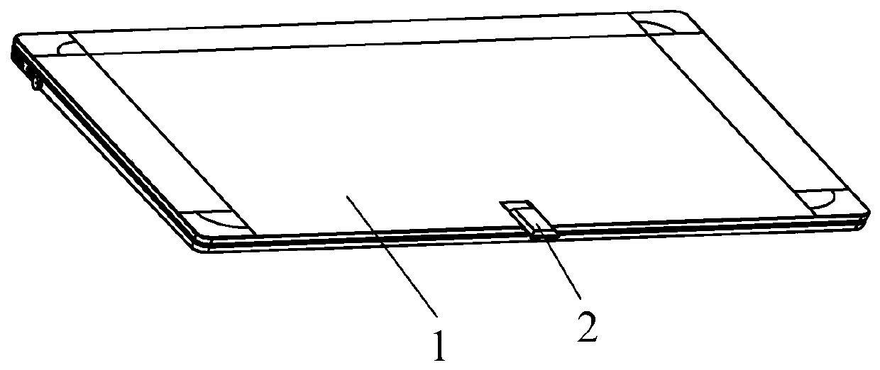
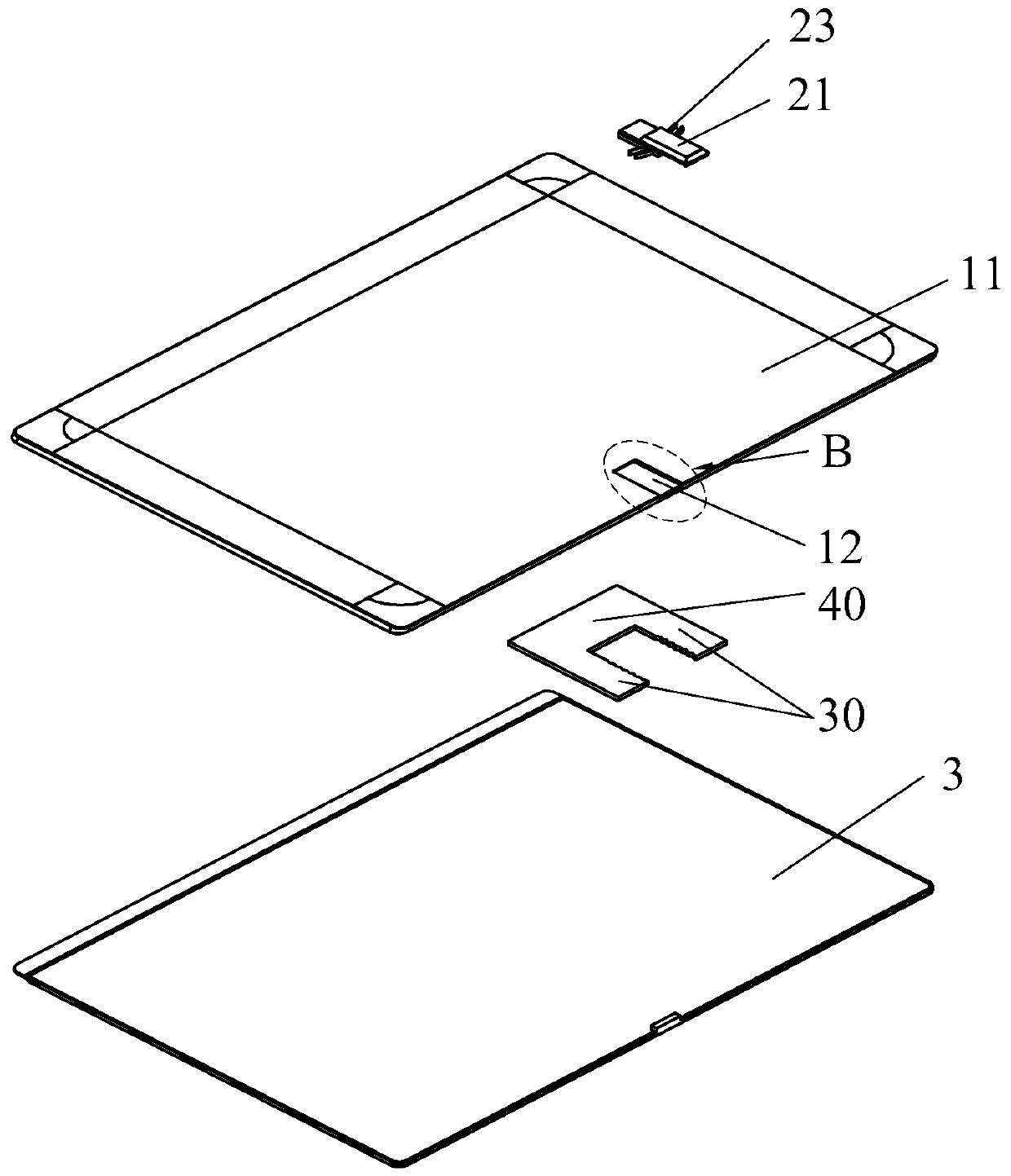
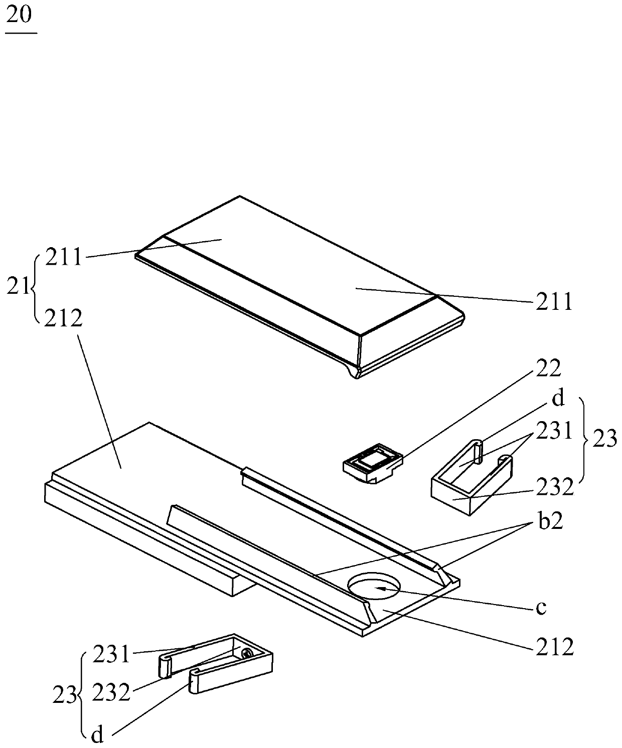
[0028] See figure 1 and figure 2 , the present invention provides an electronic device, comprising a device housing 1 and a camera device 2 arranged on the device housing 1, the camera device 2 can complete the camera 22 (such as Figure 4 ) is concealed or protru...


PUM


Abstract

The invention provides a camera device which comprises two positioning bodies which are transversely arranged at an interval, and at least one clamping position is formed on each of the opposite sidewalls of the two positioning bodies; and a camera assembly which is arranged between the two positioning bodies in a longitudinal sliding manner; the camera assembly comprises a mounting shell, a camera body arranged in the mounting shell and elastic pieces fixed to the two transverse sides of the mounting shell correspondingly. One end of the elastic piece is fixed on the mounting shell; the other end of the elastic piece is clamped at the corresponding clamping position; when the other end of the elastic piece is clamped at the corresponding clamping position; the mounting shell is longitudinally pushed to drive the elastic piece located at the first swing position to be elastically bent and restored so as to swing to the second swing position or drive the elastic piece located at the second swing position to be elastically bent and restored so as to swing to the first swing position. Therefore, the camera assembly can slide telescopically relative to the electronic device to hide the camera. The invention also provides electronic equipment comprising the camera device.

Description

technical field [0001] The invention relates to the field of camera technology, in particular to a camera device and electronic equipment. Background technique [0002] At present, with the rapid development of electronic products, people pay more and more attention to the protection of personal privacy. However, at present, the cameras of many electronic devices are exposed to the outside. When users do not need to use the cameras, they cannot be hidden. Sometimes user privacy Leakage and other situations may cause safety hazards to users. In order to solve the above problems, a hidden camera has emerged. When it is not in use, it can be hidden inside the electronic device. However, the movement and positioning structure of the current hidden camera is complicated, which is not conducive to the reliability of camera movement. It is not conducive to the miniaturization design of electronic equipment. In addition, the cameras of most electronic devices currently on the mark...

Claims


Application Information

Patent Timeline
Patent Type & Authority Applications(China)
IPC IPC(8): H04N5/225
CPCH04N23/50H04N23/57
Inventor 陈新明
Owner GUANGDONG HONGQIN COMM TECH CO LTD
Learn More