Waste incineration system

A waste incineration and rotating shaft technology, applied in the direction of incinerators, combustion methods, combustion types, etc., can solve the problems of resource waste and low efficiency, and achieve the effect of simplifying equipment structure and saving resources

Active Publication Date: 2019-08-30
温州转宇纺织有限公司
View PDF5 Cites 3 Cited by
  • Summary
  • Abstract
  • Description
  • Claims
  • Application Information

AI Technical Summary

Problems solved by technology

[0002] When people incinerate waste, the heat generated by incineration cannot be used, resulting in waste of resources. Now there are some waste incineration systems with waste heat recovery, but the waste heat is mostly used for power generation, and the efficiency is low. Therefore, there is an urgent need for a waste incineration system to solve the problem. above question

Method used


Image

  • Waste incineration system
  • Waste incineration system
  • Waste incineration system

Examples


Embodiment Construction

[0013] All features disclosed in this specification, or steps in all methods or processes disclosed, may be combined in any manner, except for mutually exclusive features and / or steps.

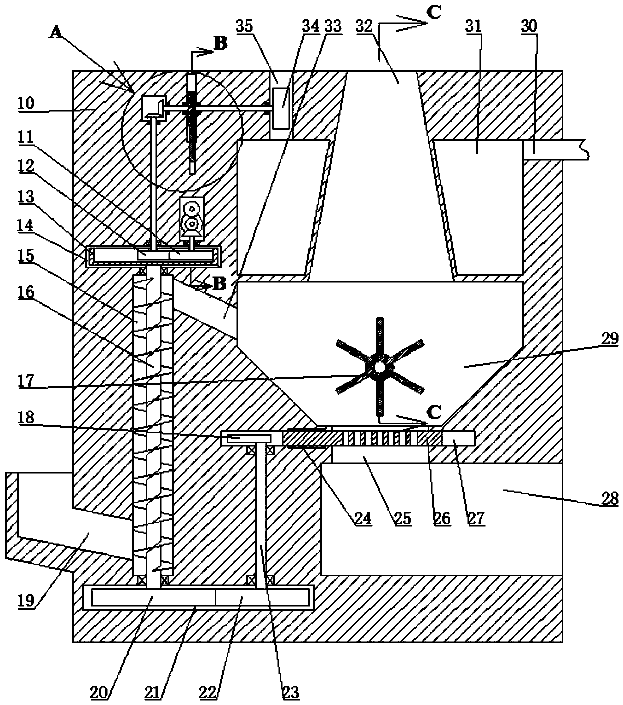
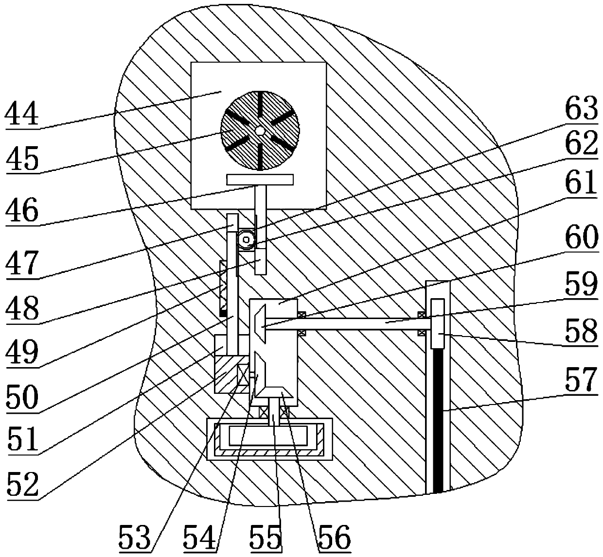
[0014] Combine below Figure 1-4 The present invention is described in detail, wherein, for the convenience of description, the orientations mentioned below are defined as follows: figure 1 The up, down, left, right, front and back directions of the projection relationship itself are the same.

[0015] Such as Figure 1-4 As shown, a kind of waste incineration system of the present invention includes a fuselage 10, an incineration chamber 29 and a feeding chamber 15 arranged in the fuselage 10, a flue 32 is arranged in the top wall of the incineration chamber 29, and the A steam chamber 31 surrounds the circumferential wall of the flue 32, a water inlet 30 is provided in the right side wall of the steam chamber 31, an air outlet 35 is provided in the top wall of the steam chamber 31, and an ...


PUM


Abstract

The invention provides a waste incineration system. The waste incineration system comprises an airframe, an incineration chamber and a feeding chamber arranged in the airframe, wherein a flue passageis arranged in the top wall of the incineration chamber; the circumferential wall of the flue passage is surrounded by steam chambers; water inlet holes are formed in the right side walls of the steamchambers; air outlets are formed in the top walls of the steam chambers; centrifugal chambers are arranged in the left walls of the air outlets; drive chambers are arranged in the left side walls ofthe centrifugal chambers; first rotating shafts penetrating through the centrifugal chambers are rotationally arranged between the drive chambers and the air outlets; the outer surfaces of the first rotating shafts in the drive chambers are fixedly provided with first bevel gears; and turbofans are fixedly arranged on the outer surfaces of the first rotating shafts in the air outlets. By means ofthe waste incineration system, the feeding and ash screening of the system can be achieved by using the same power source, so that the system structure is simplified; and meanwhile, the system recycles waste heat from waste incineration to provide power for the system, so that resources are saved.

Description

technical field [0001] The invention relates to the field of garbage treatment, in particular to a garbage incineration system. Background technique [0002] When people incinerate waste, the heat generated by incineration cannot be used, resulting in waste of resources. Now there are some waste incineration systems with waste heat recovery, but the waste heat is mostly used for power generation, and the efficiency is low. Therefore, there is an urgent need for a waste incineration system to solve the problem. above question. Contents of the invention [0003] The object of the present invention is to provide a garbage incineration system, which can overcome the above-mentioned defects of the prior art and improve the practicability of the equipment. [0004] A garbage incineration system of the present invention comprises a fuselage, an incineration chamber and a feeding chamber arranged in the fuselage, a flue is arranged in the top wall of the incineration chamber, and...

Claims


Application Information

Patent Timeline
Patent Type & Authority Applications(China)
IPC IPC(8): F23G5/00F23G5/46F23G5/44
CPCF23G5/00F23G5/444F23G5/46F23G2205/121F23G2206/203Y02E20/12
Inventor 不公告发明人
Owner 温州转宇纺织有限公司
Why Eureka
Try Eureka