
Pipeline welding auxiliary device and manufacturing method thereof

A technology for auxiliary devices and pipes, applied in welding accessories, tubular items, other household appliances, etc., can solve problems such as waste of manpower and material resources, hidden dangers, and poor use of fire buckets.

Inactive Publication Date: 2019-08-30
CHINA MCC5 GROUP CORP
View PDF12 Cites 0 Cited by
  • Summary
  • Abstract
  • Description
  • Claims
  • Application Information

AI Technical Summary

Problems solved by technology

[0003] The current windshield device for pipeline welding is to build a windshield or a windshield, which has the following disadvantages: First, the welding position of the pipeline needs to be changed in various positions, and it will waste a lot of manpower and labor to install and remove these windshields or windshields. material resources
The second is that the diameters of the pipes are different. These windshields or windshields have poor adaptability to different pipe diameters. When the diameter of the pipes changes, the windshield effect of the same type of windshields or windshields will become worse.
The third is that the welding part of the pipeline needs to be moved and changed frequently, and the traditional fixed-position fire bucket is not effective, and some high-temperature substances such as sparks that have not been connected are easy to float out of the fire bucket, which brings safety hazards

Method used


Image

  • Pipeline welding auxiliary device and manufacturing method thereof
  • Pipeline welding auxiliary device and manufacturing method thereof
  • Pipeline welding auxiliary device and manufacturing method thereof

Examples


Embodiment Construction

[0028] The following will clearly and completely describe the technical solutions in the embodiments of the present invention with reference to the accompanying drawings in the embodiments of the present invention. Obviously, the described embodiments are only some, not all, embodiments of the present invention. Based on the embodiments of the present invention, all other embodiments obtained by persons of ordinary skill in the art without making creative efforts belong to the protection scope of the present invention.

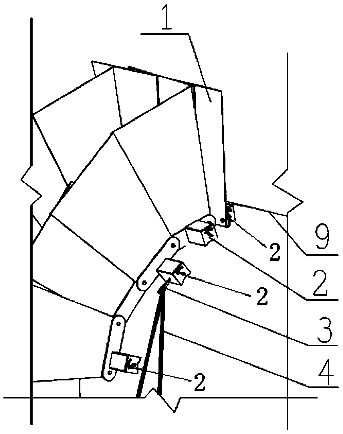
[0029] like Figure 1 to Figure 5 The pipeline welding auxiliary device provided by the illustrated embodiment of the present invention includes two windshield assemblies 1 arranged at intervals, the windshield assembly 1 has a plurality of windshields 11, and one of the windshields 11 are connected to each other and overlap each other, and are suitable for rotating with the connection point as the axis to make the windshield assembly 1 bend and fit the outer ...


PUM


Abstract

The invention relates to a pipeline welding auxiliary device and a manufacturing method thereof. The pipeline welding auxiliary device comprises two wind shield assemblies arranged in a spaced mannerand switching type magnetic seats. Each wind shield assembly is provided with multiple wind shields. The multiple wind shields of each wind shield assembly are connected and are suitable for rotatingwith the connecting point as the axis so that the wind shield assembly can be bent and attached to the outer portion of a pipeline. The switching type magnetic seats are connected to the wind shield assemblies and are detachably connected with the pipeline. The pipeline welding auxiliary device further comprises a fire receiving hopper and a steel wire rope connected with the fire receiving hopper. The fire receiving hopper is suspended on the switching type magnetic seats through the steel wire rope. The pipeline welding auxiliary device has the advantages that manufacturing and mounting aresimple and fast, and adaptability to different pipe diameters and welding positions is good, and the pipeline welding auxiliary device can be widely applied to pipe welding work.

Description

technical field [0001] The invention relates to the technical field of pipeline welding, in particular to a pipeline welding auxiliary device and a manufacturing method thereof. Background technique [0002] Many construction projects, metallurgical construction, petrochemical, municipal engineering, etc. need welding work when installing outdoor pipelines. When welding pipelines, there are certain requirements for the wind speed of the welding environment. Arc welding cannot exceed 8m / s, and CO2 cannot exceed 2m / s. This requires a windshield device to be installed around the welding part of the pipeline to meet the requirements of the welding environment of the pipeline on site; in addition, when welding pipelines at high altitudes, weld slag, sparks, and other high-temperature substances produced by high-temperature welding and gas cutting will also fall to the ground , these falling high-temperature substances are blown around by the wind, which will not only threaten the...

Claims


Application Information

Patent Timeline
IPC IPC(8): B23K9/32B23K101/06
CPCB23K9/32B23K2101/06
Inventor 蔡静
Owner CHINA MCC5 GROUP CORP
Learn More