
Lighting device and corresponding method

A lighting device, the technology of the opposite end, which is applied in the direction of lighting devices, components of lighting devices, lighting and heating equipment, etc., can solve the problems of limited extension range

Active Publication Date: 2021-08-24
CLAY PAKY
View PDF5 Cites 0 Cited by
  • Summary
  • Abstract
  • Description
  • Claims
  • Application Information

AI Technical Summary

Problems solved by technology

[0008] Furthermore, the various solutions may present limitations with regard to the extent of the area over which (more or less) uniform illumination can be obtained

Method used


Image

  • Lighting device and corresponding method
  • Lighting device and corresponding method
  • Lighting device and corresponding method

Examples


Embodiment Construction

[0036] In the following description, various specific details are given in order to provide a thorough understanding of various exemplary embodiments of the specification. Embodiments may be practiced without one or several of the specific details, or with other methods, components, materials, and the like. In other instances, well-known structures, materials, or operations are not shown or described in detail to avoid obscuring aspects of the various embodiments. Throughout this specification, reference to "one embodiment" or "an embodiment" means that a particular feature, structure, or characteristic described in connection with the embodiment is included in at least one embodiment. Thus, the appearances of the phrases "in one embodiment" or "in an embodiment" in various places throughout this specification are not necessarily all referring to the same embodiment. Furthermore, the particular features, structures or characteristics may be combined in any suitable manner in ...


PUM


Abstract

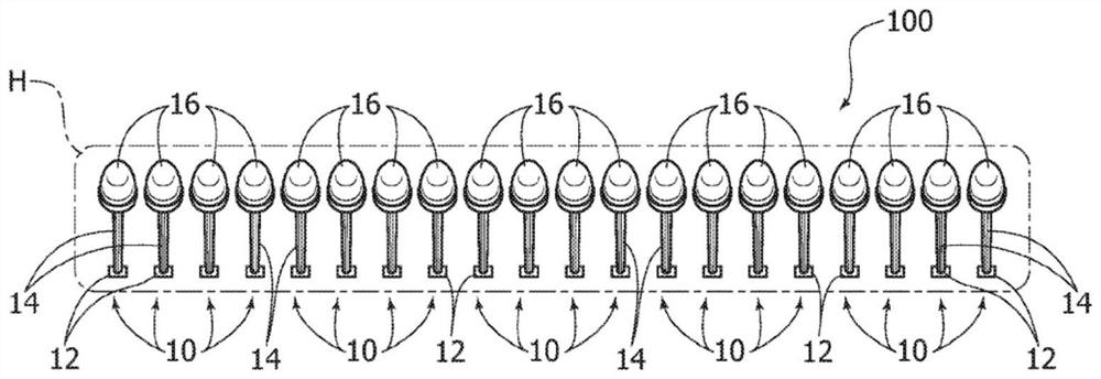
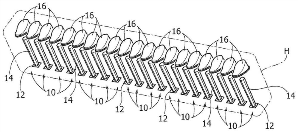
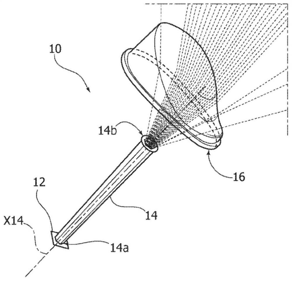
A lighting device, for example for flood lighting applications, comprising a linear array of light radiation emitters (10) comprising a light radiation source, such as an LED source (12) a light guiding member (14), the light guiding member (14) has a first end and a second end (14b), the first end is coupled to a radiation source, and the second end (14b) is used for emit light radiation guided by the light guide member (14) along the guide axis; and an optical system (16) for receiving the light radiation from the light guide member (14) and from the lighting device (100) Projecting outgoing optical radiation. The light-guiding members (14) of the optical radiation emitters (10) in the array are arranged such that the second ends of the light-guiding members are aligned along the longitudinal direction (z) of the array and the light-guiding axis of the light-guiding members is at in a common plane at an angle to the datum plane. An optical system (16) of an optical radiation emitter (10) in the array generates an outgoing optical radiation beam having a higher angle relative to the reference plane than a corresponding input beam.

Description

technical field [0001] This specification relates to lighting devices. [0002] One or more embodiments may relate to a lighting device suitable for implementing so-called wall lighting / flood lighting, wherein light radiation illuminates an extension of a surface, eg a wall. Background technique [0003] On the market, there are known various lighting solutions suitable for implementing this lighting effect by adopting refractive systems, eg using lenses, or by employing reflective systems, eg using reflectors. [0004] Some solutions may consist of simple optical systems such as flat reflectors surrounding a Lambertian (eg LED) optical radiation source with a broad radiation distribution. [0005] This solution may have the disadvantage that the luminaire has to be placed at a considerable distance (up to 3 meters or more) from the illuminated surface in order to obtain a good level of illuminance uniformity. [0006] Other solutions employ more complex specialized optics...

Claims


Application Information

Patent Timeline
IPC IPC(8): G02B6/00F21V5/00F21V5/08F21Y103/10F21Y115/10
CPCF21V5/007F21V5/08G02B6/0001F21Y2103/10F21Y2115/10G02B6/0073G02B6/0075
Inventor 雷纳托·弗里索阿尔贝托·阿尔菲耶尔黎小珑卢卡·马斯科洛
Owner CLAY PAKY
Learn More