
Device for overcoming blasting foundation

A basic and circular technology, applied in the field of devices for overcoming blasting foundations, can solve the problems of difficulty in drilling operations in the next cycle, increasing construction costs, and increasing blasting operation costs.

Inactive Publication Date: 2019-08-27
SHANDONG UNIV OF SCI & TECH
View PDF8 Cites 4 Cited by
  • Summary
  • Abstract
  • Description
  • Claims
  • Application Information

AI Technical Summary

Problems solved by technology

If there is no super-deep part of this part, due to the sandwiching effect of the rock, the blasting effect will not reach the design step height, and the foundation will be generated. When dealing with the foundation, a large amount of secondary blasting expenses will be invested, which increases the construction cost, and it is easy to produce Flying rocks during blasting seriously affect blasting safety; if this part is set to be super deep, the blasting effect will be significantly improved, but the rock near the blast hole will be over-excavated and broken, which will bring difficulties to the next drilling cycle and increase the drilling depth , increased the consumption of explosives, and greatly increased the cost of blasting operations. Although the blasting effect was improved after setting the ultra-deep, the explosives in the ultra-deep part could not be fully utilized due to the sandwiching effect of the rock.

Method used


Image

  • Device for overcoming blasting foundation
  • Device for overcoming blasting foundation

Examples


Embodiment Construction

[0022] The specific embodiment of the present invention will be further described below in conjunction with accompanying drawing and specific embodiment:

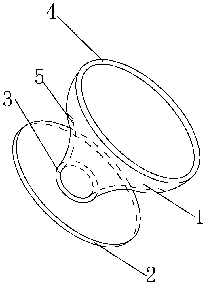
[0023] Such as figure 1 and figure 2 As shown, a device for overcoming the root of blasting includes an integrally formed charge fixing part 1 and a circular steel plate 2. The charge fixing part is in the shape of a funnel with an arc-shaped inner surface, and includes an upper charge fixing cavity and a circular steel plate 2. In the lower energy-gathering cavity, the funnel-shaped small head faces one side of the circular steel plate.

[0024] The inner surface of the energy-gathering cavity is covered with a layer of copper sheet 5, which is beneficial to transform the shock wave generated by the explosion into a high-energy metal jet, and further expands the lateral action range.

[0025] The opening of the funnel-shaped big head of the charge fixing part is a big circle 4, and the diameter of the big circle 4 is 0....


PUM

PropertyMeasurementUnit
Heightaaaaaaaaaa
Thicknessaaaaaaaaaa
Diameteraaaaaaaaaa

Abstract

The invention discloses a device for overcoming a blasting foundation, and particularly relates to the technical field of engineering blasting. The device comprises an explosive column fixing part anda round steel plate, wherein the explosive column fixing part and the round steel plate are integrally formed, the explosive column fixing part is provided with a funnel shape arc-shaped inner surface and comprises a explosive column fixing cavity at the upper part and an energy gathering cavity at the lower part, a funnel-shaped small head faces towards one side of the round steel plate, the round steel plate can reflect the shock wave generated during blasting, the energy gathering cavity has the energy gathering function, the explosion energy density can be improved, the inner surface of the energy gathering cavity is covered with a layer of red copper sheet, the shock wave generated by explosion is converted into high-energy metal jet flow, the transverse action range is further expanded, an opening of the funnel-shaped big head of the explosive column fixing part is provided with a large circle, the diameter of the large circle is 0.8-0.9 time of the diameter of blast hole, and the diameter of the large circle is 1.05 times of the diameter of the explosive; the opening of the funnel-shaped small head of the explosive column fixing part is provided with a small circular shape,the small circle is a guide hole, the diameter of the small circle is smaller than the diameter of the large circle, the diameter of the small circle is 0.4-0.5 time of the diameter of blast hole.

Description

technical field [0001] The invention relates to the technical field of engineering blasting, in particular to a device for overcoming blasting roots. Background technique [0002] At present, in the step blasting operation, most of them are faced with a problem. Considering the blasting effect, in order to overcome the blasting root, ultra-deep drilling will be considered during the drilling process, and a certain amount of explosives needs to be loaded into the ultra-deep part. If there is no super-deep part of this part, due to the sandwiching effect of the rock, the blasting effect will not reach the design step height, and the foundation will be generated. When dealing with the foundation, a large amount of secondary blasting expenses will be invested, which increases the construction cost, and it is easy to produce Flying rocks during blasting seriously affect blasting safety; if this part is set to be super deep, the blasting effect will be significantly improved, but ...

Claims


Application Information

Patent Timeline
IPC IPC(8): F42D1/00F42D3/04
CPCF42D1/00F42D3/04
Inventor 高文乐李坤鹏孙晓娟苏凯凯
Owner SHANDONG UNIV OF SCI & TECH
Learn More