
Coal cinder cleaning device for thermal power plant

A technology for thermal power plants and cleaning devices, which is applied to grain processing, lighting and heating equipment, etc. It can solve the problems of unclean cleaning, more cinders remaining, and cinders that cannot be completely removed, and achieve the effect of avoiding incomplete cleaning

Active Publication Date: 2019-08-27
大唐东营发电有限公司
View PDF5 Cites 4 Cited by
  • Summary
  • Abstract
  • Description
  • Claims
  • Application Information

AI Technical Summary

Problems solved by technology

[0004] Most of the traditional cinder cleaning devices are carried out by ash cleaning equipment, but the traditional ash cleaning equipment is prone to cleaning unclean when cleaning the cinder inside the cold slag hopper. It cannot be completely removed, resulting in a large amount of cinder remaining after cleaning the inside of the cold slag hopper

Method used


Image

  • Coal cinder cleaning device for thermal power plant
  • Coal cinder cleaning device for thermal power plant
  • Coal cinder cleaning device for thermal power plant

Examples


Embodiment Construction

[0023] The following will clearly and completely describe the technical solutions in the embodiments of the present invention with reference to the accompanying drawings in the embodiments of the present invention. Obviously, the described embodiments are only some, not all, embodiments of the present invention. Based on the embodiments of the present invention, all other embodiments obtained by persons of ordinary skill in the art without making creative efforts belong to the protection scope of the present invention.

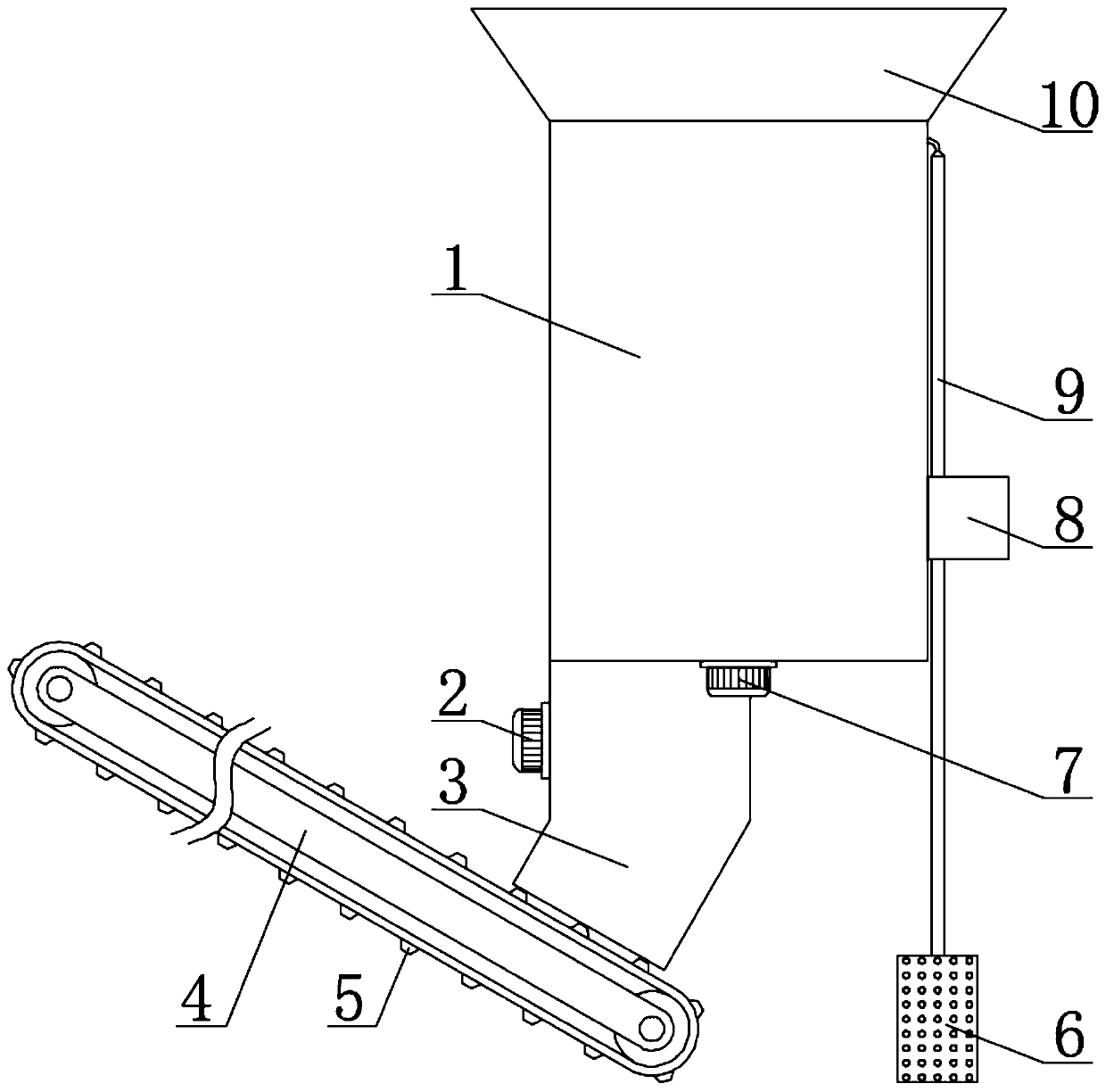
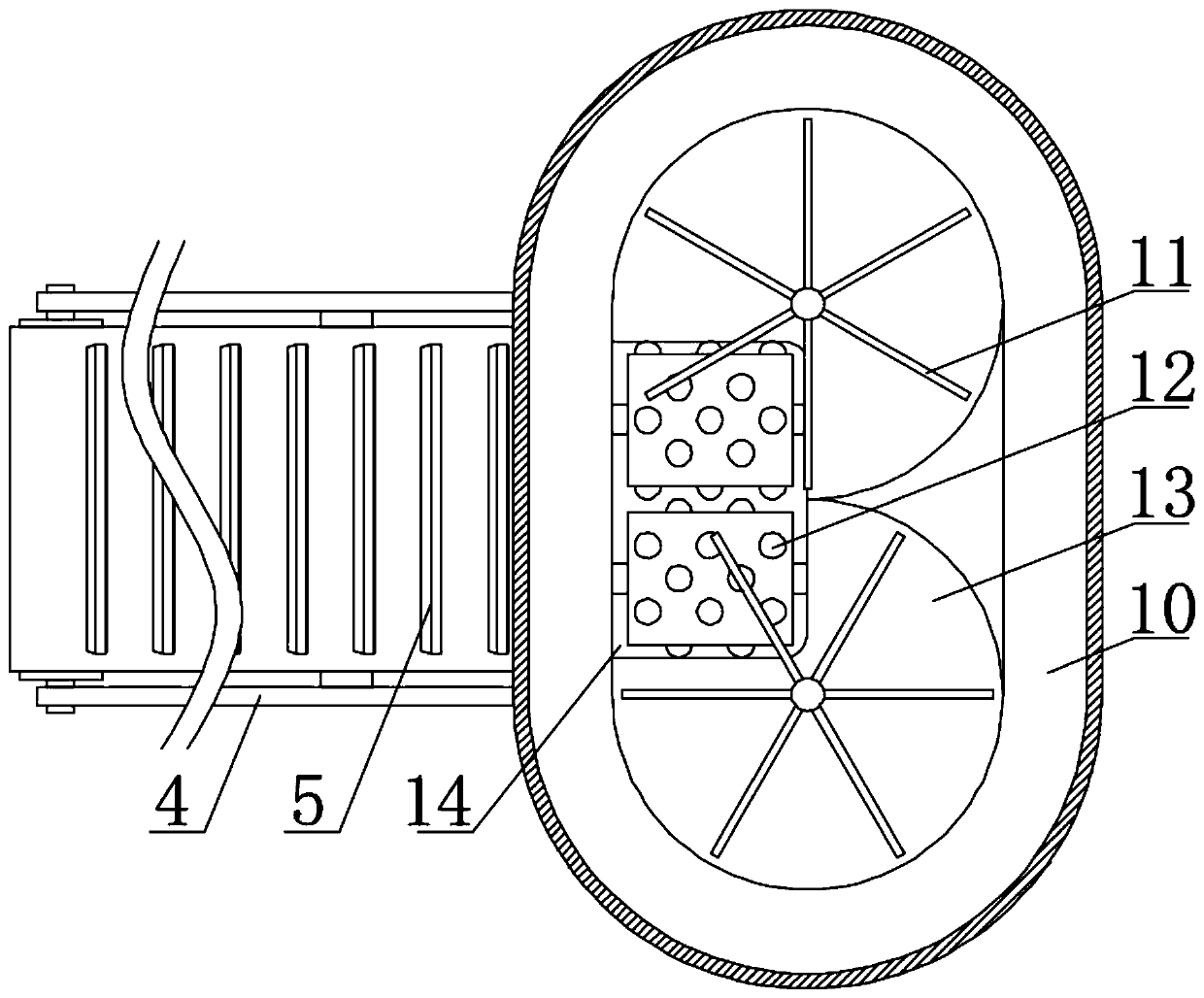
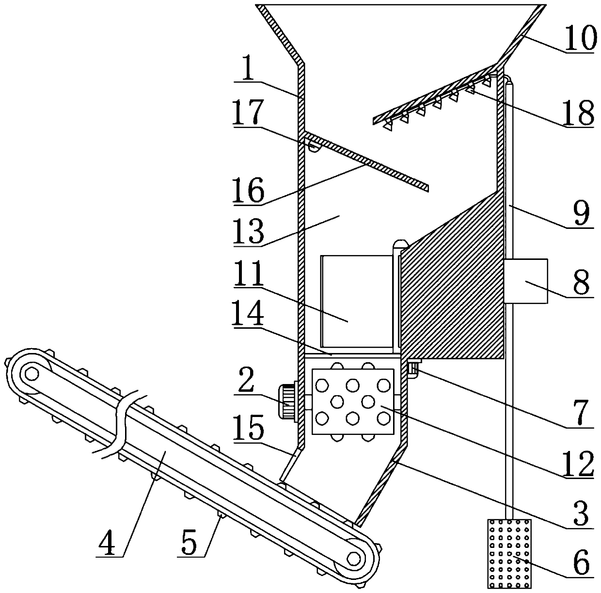
[0024] see Figure 1-4 , the present invention provides a technical solution: a coal slag cleaning device for a thermal power plant, characterized in that it includes a coal slag collection shell 1, a discharge shell 3, a crushing roller 12 and a microprocessor 19: inside the coal slag collection shell 1 Two cylindrical collection chambers 13 are fixedly provided, and the collection chambers 13 are used to collect cinder waste, and the cinder collection shell ...


PUM


Abstract

The invention discloses a coal cinder cleaning device for a thermal power plant. The coal cinder cleaning device comprises a coal cinder collecting shell, a discharging shell, crushing rollers and a microprocessor. Two cylindrical collecting cavities are fixedly formed in the coal cinder collecting shell and used for collecting coal cinder waste. Discharging outlets used for discharging coal cinder are formed in the sides, located at the bottoms of the collecting cavities, of the coal cinder collecting shell. Two receiving motors are fixedly installed on the lower surface of the coal cinder collecting shell through screw spikes, the receiving motors are electrically connected with the signal end of the microprocessor, and the power output ends of the receiving motors are fixedly welded with receiving plates. The coal cinder can be concentrated in the collecting cavities and then pushed into the discharging outlets by means of the receiving plates in the collecting cavities, because thecollecting cavities are cylindrical and the receiving plates can be exactly matched with the inner walls of the collecting cavities during rotation, the receiving plates can clean all the coal cinderin the collecting cavities, and incomplete cleaning o the coal cinder is avoided.

Description

technical field [0001] The invention relates to the technical field of accessories for coal-fired steam boilers, in particular to a coal slag cleaning device for thermal power plants. Background technique [0002] Thermal power generation is a power generation method that converts the heat energy generated by combustible materials into electrical energy through a power generation device; there are three types of energy conversion processes in thermal power generation: fuel chemical energy-steam thermal energy-mechanical energy-electrical energy, Simply put, it uses fuel to generate heat, heats water, and forms high-temperature and high-pressure superheated steam, and then the steam enters the steam turbine along the pipeline to continuously expand and do work, impacting the turbine rotor to rotate at high speed, driving the generator rotor (electromagnetic field) to rotate, the stator coil cuts the magnetic field lines, and generates electric energy , and then use the step-u...

Claims


Application Information

Patent Timeline
Patent Type & Authority Applications(China)
IPC IPC(8): F23J1/06B02C4/08B02C4/30
CPCB02C4/08B02C4/30B02C2201/06F23J1/06
Inventor 李玮王国金贾长武倪培林周恩浩田润平
Owner 大唐东营发电有限公司
Learn More