
Tire burst emergency device

An emergency device and tire blowout technology, which is applied to tire parts, transportation and packaging, vehicle parts, etc., can solve the problems of high cost, heavy weight, and increased vehicle weight, and achieve the effect of light weight and increased weight

Pending Publication Date: 2019-08-27
NINGBO TAIKEWEI RUBBER TECH CO LTD
View PDF0 Cites 0 Cited by
  • Summary
  • Abstract
  • Description
  • Claims
  • Application Information

AI Technical Summary

Problems solved by technology

[0006] In the prior art, small plastic nylon advances are bonded to metal cast iron, and the small components are connected by pins, adjusted according to the size of the wheel, and then installed on the wheel by screws, or the main body of the product is cast iron, and the finished product is assembled The weight of the rear is very heavy, it needs casting molding process, the cost is extremely high, and it is installed on the wheel, which increases the weight of the vehicle, increases the fuel consumption of the vehicle, and increases the centrifugal inertia of the vehicle when driving at high speed

Method used


Image

  • Tire burst emergency device
  • Tire burst emergency device
  • Tire burst emergency device

Examples


Embodiment 1

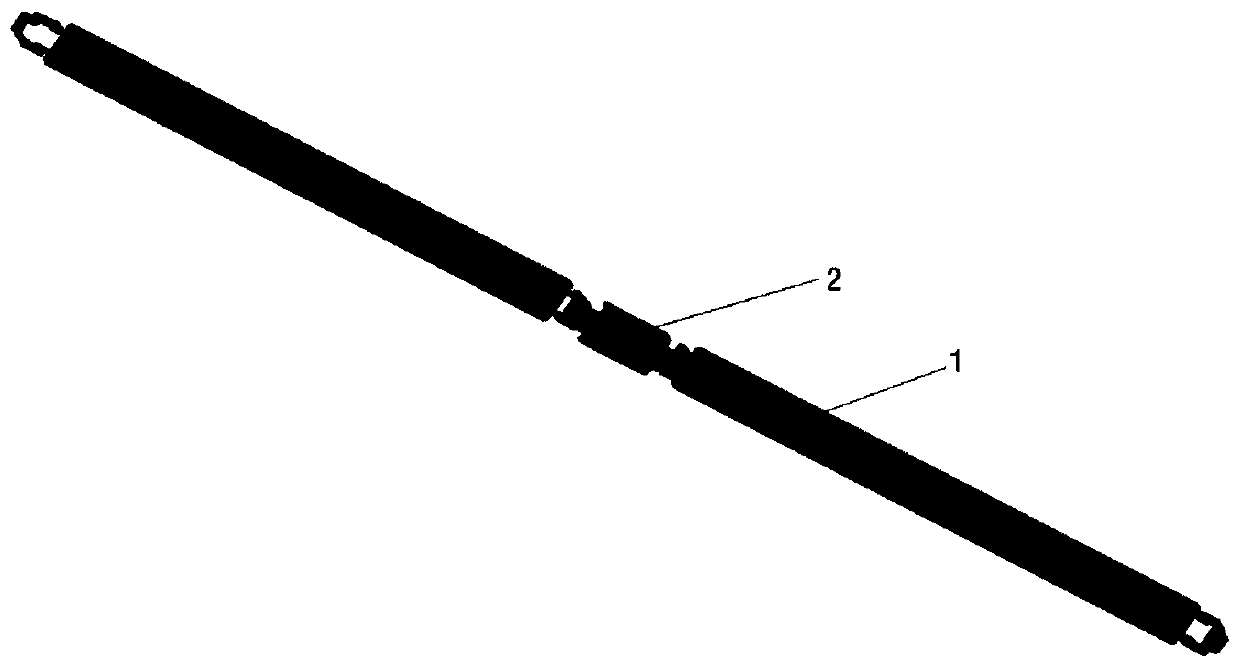
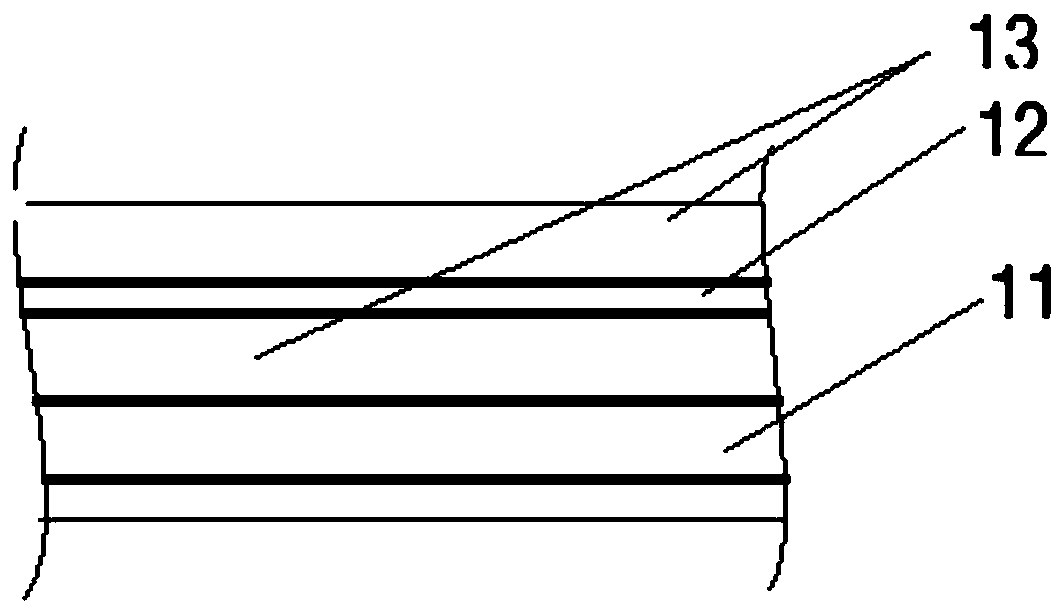
[0039] Tire burst emergency device of the present invention, see figure 1 and figure 2As shown, it includes: a belt-shaped body formed by connecting explosion-proof belt units 1 in series, and the belt-shaped body is circumferentially arranged in close contact with the surface of the hub. The explosion-proof belt unit includes a lower manganese steel layer 11 and an upper cord fabric layer 12, and the rubber layer 13 separates and wraps the manganese steel layer 11 and the cord fabric layer 12 through vulcanization. Two adjacent explosion-proof units are assembled by means of rubber circlip pins. The carcass layer 12 is located between the rubber 13 and the manganese steel layer 11 at a position of one-third to two-thirds. The outermost surface of the main rubber layer adopts a plum pattern pattern such as Figure 5 shown.

[0040] The above-mentioned device is composed of various parts. The main part is composed of rubber, high and low temperature resistant manganese ste...

Embodiment 2

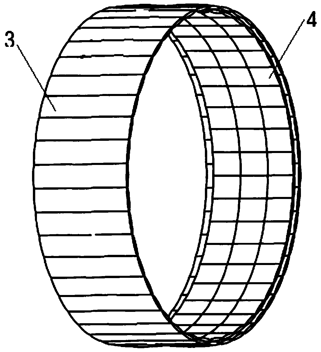
[0042] Tire burst emergency device of the present invention, see image 3 As shown, the explosion-proof band unit includes a unit capsule 3 and a shear thickening liquid filled in the capsule 3 .

[0043] Specifically, the height of the bladder is 1 / 3-2 / 3 of the height from the inner surface of the tire to the hub. The capsule is made of rubber or polymer material with strong flexibility; the thickness of the capsule is 3.0mm-5.0mm. The shear thickening liquid is a non-Newtonian fluid filling material, and the shear thickening liquid is water starch or a stable suspension liquid dissolved in polyethylene glycol or ethylene glycol.

[0044] Preferably, the sealed airbag 4 is bonded to the lower part of the capsule 3 filled with the shear thickening liquid, so as to prevent the apparent viscosity of the explosion-proof belt from increasing exponentially in milliseconds and causing damage to the hub when it becomes a hard solid.

[0045] The technical indicators of the comprehe...


PUM

PropertyMeasurementUnit
Thicknessaaaaaaaaaa

Abstract

The invention discloses a tire burst emergency device. The tire burst emergency device comprises a belt-shaped body formed by series connection of explosion-proof belt units, the belt-shaped body is circumferentially attached to the surface of a hub, the explosion-proof belt units comprise manganese steel layers arranged at the lower part and tyre fabrics layers on the upper part, the manganese steel layers and the tyre fabrics layers are separated by rubber layers through vulcanization and wrapped with the rubber layers, or the explosion-proof belt units comprise a plurality of unit capsulesand shear thickening liquids filled in the capsules. According to the tire burst emergency device, the weight is effectively lightened, a tire is supported when the tire bursts, the tire is preventedfrom falling off from the hub, and a vehicle is further prevented from overturning due to loss balance at the moment of the tire burst.

Description

technical field [0001] The invention relates to a tire blowout emergency safety mechanism, in particular to an automobile tire blowout device, an automobile tire blowout emergency safety device, and an automobile tire emergency safety device, belonging to the technical field of tire explosion protection. Background technique [0002] The scientific name of the run-flat tire is "run-flat tire", and the English abbreviation is RSC. The inflated tire sidewall is the main part to support the weight of the vehicle, especially for some tires with a large aspect ratio (the flatness ratio is the ratio of tire height to width), the sidewall is very "thick", and when the "puncture" is serious, it usually will This will cause the tire wall to burst instantly, causing the tire to lose its supporting force instantly, resulting in an immediate change in the vehicle's center of gravity, especially if the front wheel of a front-wheel drive vehicle is blown out, the momentary center of gravi...

Claims


Application Information

Patent Timeline
IPC IPC(8): B60C17/04
CPCB60C17/04B60C17/044
Inventor 田立辉郑顺奇孟辉王绍楠
Owner NINGBO TAIKEWEI RUBBER TECH CO LTD
Learn More