Line obstacle identification method based on three-dimensional imaging

A technology of obstacle recognition and three-dimensional imaging, applied in the field of obstacle recognition, can solve problems such as not being able to truly reflect the actual nature of obstacles, not specifically disclosing obstacle recognition and calculation, and being unable to recognize obstacles

Pending Publication Date: 2019-08-23
HENAN SPLENDOR SCI & TECH +1
View PDF13 Cites 5 Cited by
  • Summary
  • Abstract
  • Description
  • Claims
  • Application Information

AI Technical Summary

Problems solved by technology

However, this method has the following defects: the method uses a laser to scan a plane to obtain only a two-dimensional graphic image of the obstacle, and the two-dimensional cannot truly reflect the actual nature of the obstacle, and cannot accurately identify the obstacle. identification
However, this method has the following defects: the method discloses the use of three-dimensional point cloud images to identify obstacles, but does not specifically disclose how to identify and calculate obstacles

Method used


Image

  • Line obstacle identification method based on three-dimensional imaging
  • Line obstacle identification method based on three-dimensional imaging
  • Line obstacle identification method based on three-dimensional imaging

Examples


Embodiment 1

[0034] As attached figure 1 And figure 2 As shown, a line obstacle recognition method based on three-dimensional imaging includes the following steps:

[0035] Create a static 3D point cloud map of the surface

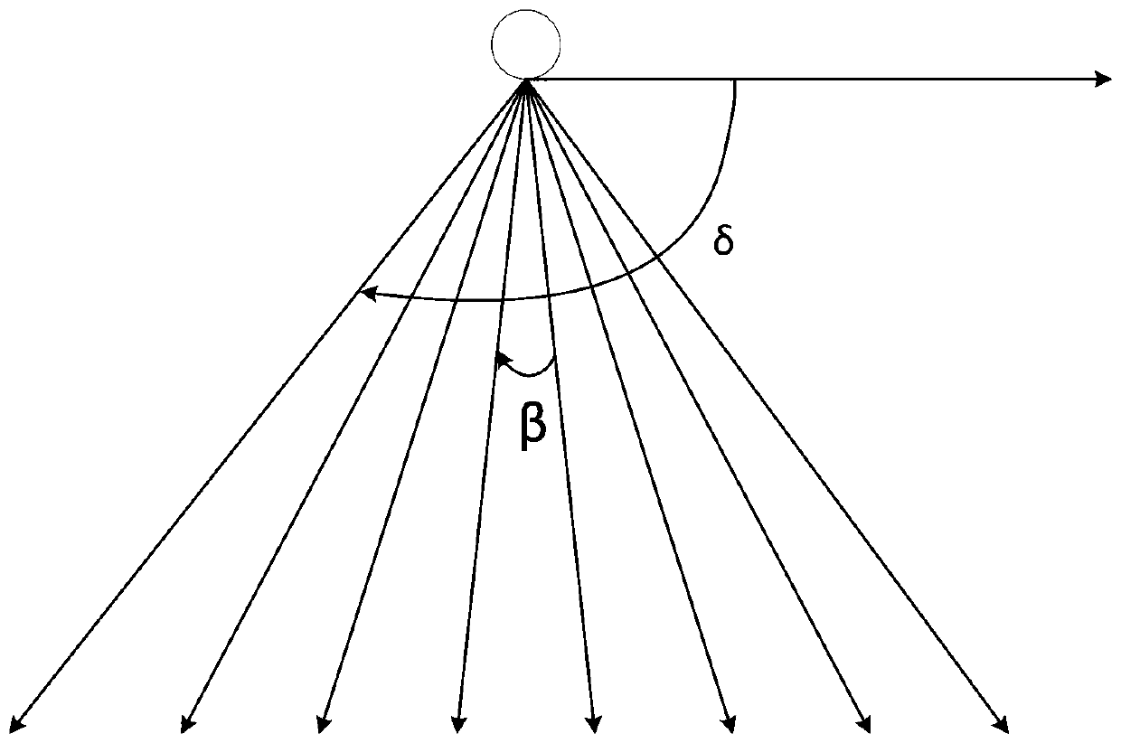
[0036] The plane lidar 1 and the angle adjustment mechanism 2 are arranged, and the scanning period of the plane lidar 1 and the rotation period of the angle adjustment mechanism 2 are set; the plane lidar 1 completes a two scan cycle Scanning of a two-dimensional plan; timing adjustment of the scanning inclination angle of the planar lidar 1 through the angle adjustment mechanism 2 to obtain N corresponding static two-dimensional scanning plan;

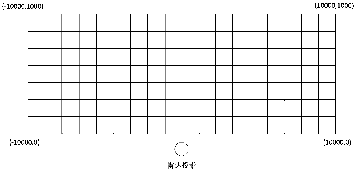
[0037] Carry out square gridding processing on the surface plane to be scanned, and divide it into several square cells, each square cell has corresponding plane coordinates;

[0038] According to the static two-dimensional scanning plan, calculate the original height Sh corresponding to each square cell to obtain a static three-dim...

Embodiment 2

[0055] This embodiment provides a specific implementation manner for obtaining a static three-dimensional point cloud image of the surface, including three steps of setting a basic static three-dimensional point cloud image of the surface, fault tolerance processing, and expansion processing.

[0056] 1) Set the static three-dimensional point cloud image of the basic surface, and the static three-dimensional point cloud image of the basic surface is the static three-dimensional point cloud image of the surface in the embodiment;

[0057] Use one of the static two-dimensional scan plan for analysis, as attached figure 1 And figure 2 As shown, the planar lidar 1 is installed on the radar hoisting rod 3. The installation height of the planar lidar is recorded as H, and the installation height H can be obtained by measurement; the current static two-dimensional scanning plan and vertical ground surface The included angle of is θ, which is the rotation angle θ of the stepping motor; the...


PUM


Abstract

The invention provides a line obstacle identification method based on three-dimensional imaging, comprising the following steps: periodically adjusting a scanning tilt angle of a planar laser radar through an angle adjustment mechanism to obtain N corresponding static two-dimensional scanning plane graphs; calculating an original height Sh corresponding to each square table cell according to the static two-dimensional scanning plane graphs, and obtaining an earth surface static three-dimensional point cloud graph; calculating a current height Dh corresponding to each square table cell according to a current two-dimensional scanning plane graph, and obtaining a current earth surface dynamic three-dimensional point cloud graph; comparing the earth surface static three-dimensional point cloudgraph with the current earth surface dynamic three-dimensional point cloud graph to obtain obstacle feature information in the current scanning period; comparing the obstacle feature information in the current scanning period with the obstacle feature information in the last scanning period to perform obstacle identification; and prompting a worker to check the railway line of the road section intime to ensure the railway running safety and personal safety and to reduce human casualty accidents inside and outside of the railway.

Description

Technical field [0001] The invention relates to an obstacle recognition method, in particular to a line obstacle recognition method based on three-dimensional imaging. Background technique [0002] The safety of railway lines is the eternal theme of railway transportation. In order to strengthen the protection and management of railway lines, ensure the safety of railway traffic and personal safety, and reduce personal injuries and death accidents inside and outside the railway, the monitoring of obstacles on the railway line through certain monitoring equipment is the railway An indispensable means in operational safety. [0003] The current Chinese patent application number 201710269081.9 discloses the "Method for Automatic Monitoring and Recognition of Railway Line Obstacles", which includes emitting a laser along a plane above the railway line in a set angle range to perform a sweep search; receiving the returned laser signal and automatically determining whether There are har...

Claims


Application Information

Patent Timeline
IPC IPC(8): G01S17/89G01S17/93G01S7/48
CPCG01S17/89G01S17/93G01S7/48
Inventor 刘大庆陈凯董少杰潘新华孙光绪铁雷雷王静
Owner HENAN SPLENDOR SCI & TECH
Why Eureka
Try Eureka