Motor vehicle lock

A technology for motor vehicles and lock tongues, applied in electric vehicle locks, vehicle locks, building locks, etc., can solve problems such as damage, and achieve the effect of simple structure and safe operation characteristics

Pending Publication Date: 2019-08-23
HUF HULSBECK & FURST GMBH & CO KG
View PDF1 Cites 1 Cited by
  • Summary
  • Abstract
  • Description
  • Claims
  • Application Information

AI Technical Summary

Problems solved by technology

The reason the cam is pulled further past the primary lock position is due to the wait or delay time of the controller which can be very easily damaged

Method used


Image

  • Motor vehicle lock
  • Motor vehicle lock
  • Motor vehicle lock

Examples


Embodiment Construction

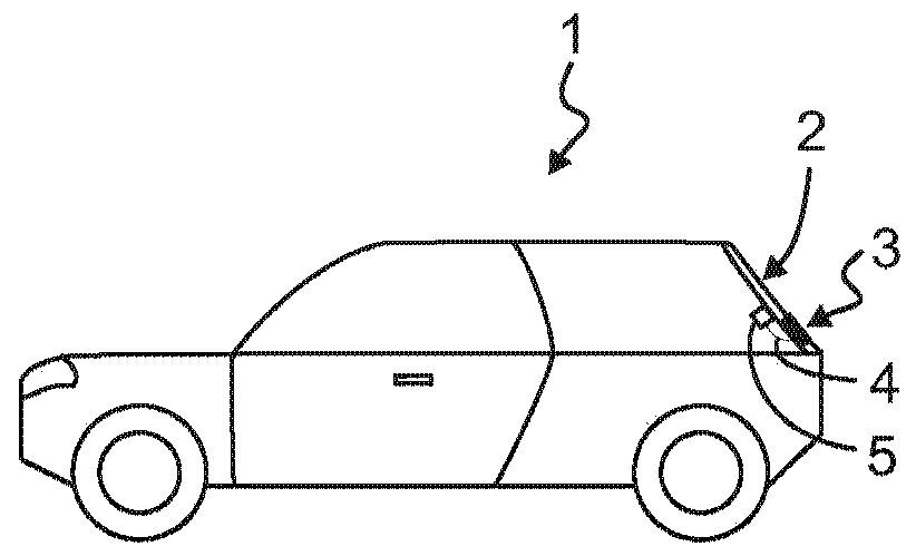
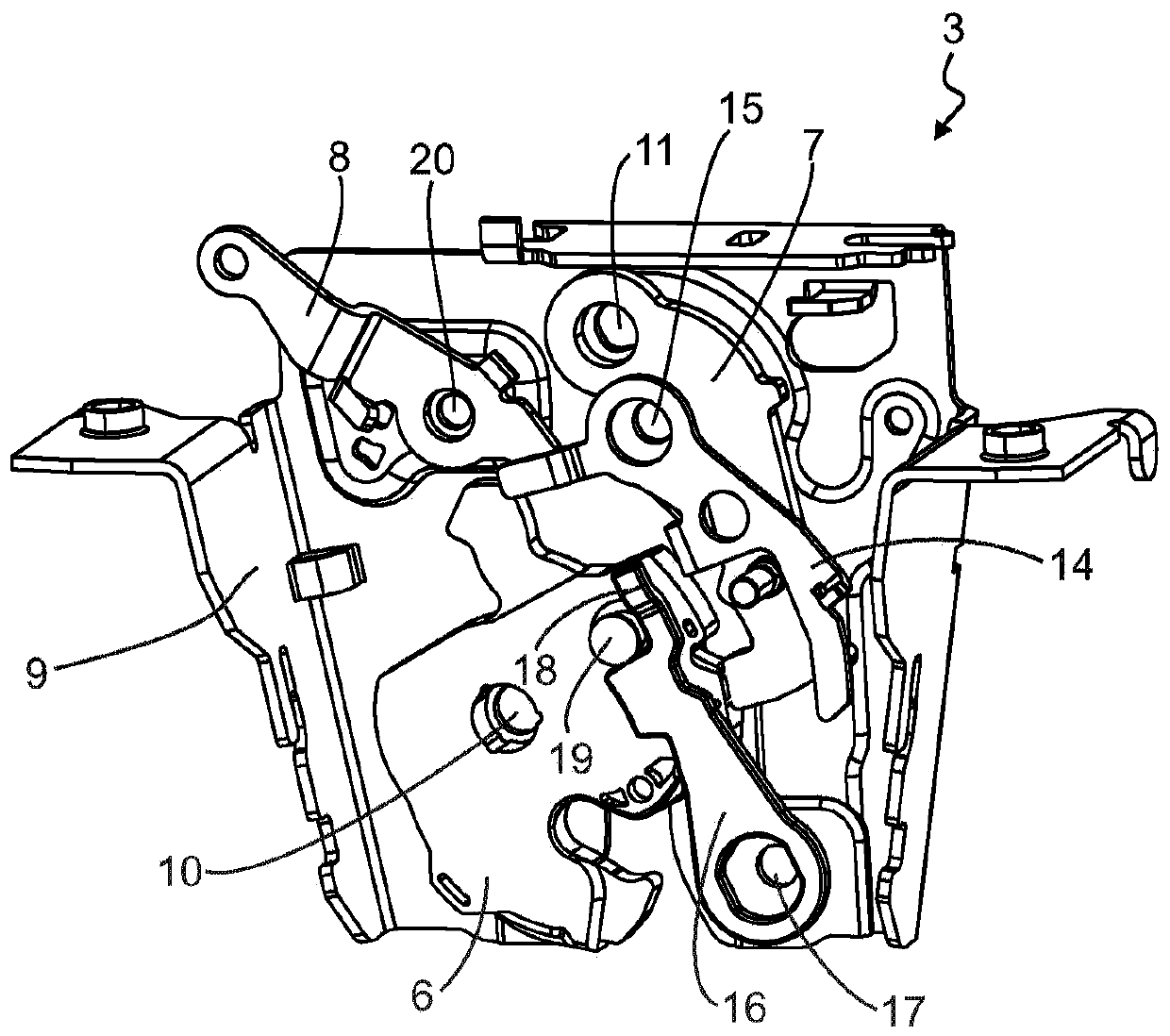
[0043] figure 1 A motor vehicle 1 in the form of a passenger vehicle is exemplarily shown in , which in the example has a trunk lid or tailgate 2 which can be closed and opened via a motor vehicle lock 3 . The motor vehicle lock 3 has a stopper, which is connected via a figure 2 The connection element 4 shown in , such as for example a soft-sleeved steel cable, is connected to the drive element 5 . The drive element 5 is implemented in this embodiment as a tensioning device and is used to automatically carry out the closing process for a stopper which currently comprises a rotary bolt 6 and a stop pawl 7 in order to make the machine The motor car lock 3 is transferred from the pre-locked state to the main locked state in a motor-driven manner. In the present embodiment, the drive element 5 moves the rotary bolt 6 coupled thereto via the tensioning rod 8, so that the rotary bolt 6 moves from the pre-locking position into the main locking position, wherein The respective tai...


PUM


Abstract

The invention relates to a motor vehicle lock with a rotatably supported rotary latch which is movable from an open position to a main latching position; a pivotally supported stopping pawl which is movable to a stop position engaged with the rotary latch arranged in its main latching position and having a latching hook; and a constraining lever pivotally supported on a carrier element in constraining positioning in which the constraining lever blocks the rotational movement of the rotary latch arranged in its main latching position. The motor vehicle lock has a deflecting device for urging the constraining lever in the direction away from the rotary latch when the rotary latch moves to its main latching position, wherein the deflecting device is connected with the constraining lever suchthat the constraining lever only pivots into its constraining positioning when the rotary latch is in its main latching position and the stopping pawl is arranged in its stop position.

Description

technical field [0001] The invention relates to a lock for a motor vehicle comprising a carrier element, a rotary bolt mounted rotatably on the carrier element, a locking pawl and a locking lever pivotably mounted on the carrier element, The rotary bolt is movable from an open position into a main locking position, the locking pawl is movable into a locking position engaging with the rotary bolt arranged in its main locking position, and the locking pawl has a locking hook , the restraint lever is pivotally supported on the carrier element in a restraint position, in which the restraint lever prevents the rotational movement of the rotary bolt arranged in its main locking position. Background technique [0002] A motor vehicle lock of the type mentioned at the outset is known, for example, from document DE 10 2012 102 724 A1. In this known motor vehicle lock, the locking pawl and the rotary bolt are rotatably mounted on a carrier element, wherein a restraining lever is prov...

Claims


Application Information

Patent Timeline
IPC IPC(8): E05B83/18E05B77/38E05B85/26
CPCE05B77/38E05B83/18E05B85/26E05B77/36E05B81/20
Inventor 斯特凡·维特坎普阿图尔·托尔卡
Owner HUF HULSBECK & FURST GMBH & CO KG
Why Eureka
Try Eureka