
Self-balancing sunshade canopy

A sunshade canopy and self-balancing technology, applied in tents/canopies, building types, buildings, etc., can solve problems such as poor support effect, achieve good use effect and avoid sunburn

Pending Publication Date: 2019-08-23
中软数信(北京)科技有限公司
View PDF0 Cites 4 Cited by
  • Summary
  • Abstract
  • Description
  • Claims
  • Application Information

AI Technical Summary

Problems solved by technology

[0004] For this reason, the embodiment of the present invention provides a self-balancing sunshade canopy to solve the problem in the prior art that the middle part of the sunshade canopy has a poor support effect due to the supporting steel wire rope with a large span.

Method used


Image

  • Self-balancing sunshade canopy
  • Self-balancing sunshade canopy
  • Self-balancing sunshade canopy

Examples


Embodiment 2

[0061] This embodiment is generally the same as Embodiment 1, only some features are different, and only the differences are described in detail below:

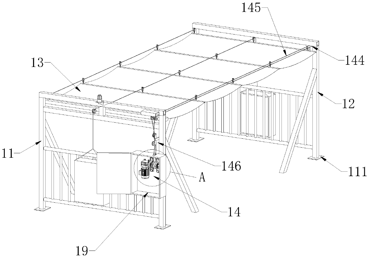
[0062] combine Figure 6 , the fixed pulley 144 is arranged on the top of the first bracket 11 away from the end of the driving device, and the two ends of the top of the second support frame are respectively provided with guide pulleys 18, and the driving cables 145 are respectively connected to the anti-slip driving pulley 1432 and the fixed pulley 144 in rotation and bypassed respectively. Two guide pulleys 18 on the second bracing frame, two points on the driving steel cable 145 with the same moving direction are fixedly connected with the movable end of the retaining cloth 13 respectively, and when the movable end of the retaining cloth 13 is driven by the driving steel cable 145, The movable end of the retaining cloth 13 can be kept in translation all the time to avoid tilting.

Embodiment 3

[0064] This embodiment is generally the same as Embodiment 1, only some features are different, and only the differences are described in detail below:

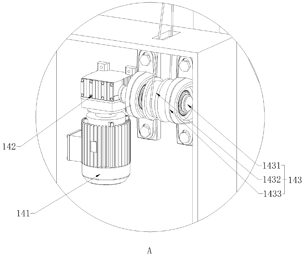
[0065] combine Figure 7 , the inner wall of the anti-slip pad 148 is provided with a connecting portion 1485, the connecting portion 1485 is an annular protrusion set along the inner wall of the anti-slip driving pulley 1432 centered on the axis of the anti-slip driving pulley 1432, and the bottom of the groove of the anti-slip driving pulley 1432 is provided with a groove along the anti-slip driving pulley 1432. The connection groove 14323 around the groove of the groove, the connection part 1485 is inserted into the connection groove 14323 and fixed, the setting of the connection part 1485 can make the anti-skid pad 148 cooperate with the anti-skid drive pulley 1432 more closely, and play a good role in preventing the anti-skid pad 148 from colliding with the anti-skid drive pulley. The pulley 1432 produces the effect of r...


PUM


Abstract

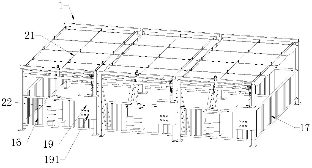
The embodiment of the invention discloses a self-balancing sunshade canopy, and belongs to the field of protective shielding equipment. According to the key points of the technical scheme, the self-balancing sunshade canopy comprises at least one shielding unit, and the shielding unit comprises a first bracket, a second bracket, shielding cloth, a driving device and a self-balancing device; the first bracket and the second bracket are arranged in parallel, and the self-balancing device comprises a slideway and counterweight devices arranged at the two ends of the slideway; the middle part of the slideway is slidably connected with the tops of the first bracket and the second bracket separately, and one end of the shielding cloth is fixedly connected with the first bracket; the other end ofthe shielding cloth is slidably connected with the middle part of the slideway, and the driving device can be used for driving the movable end of the shielding cloth to slide along the middle part ofthe slideway; and the weights of the two counterweight devices located at the two ends of the slideway separately are the same. The shielding cloth can be used for shielding the position above a tunnel; when a canopy device is wider in span, the slideway can be tensioned through the counterweight devices, and the middle part of the slideway is prevented from being sagging severely, so that the self-balancing sunshade canopy can be suitable for application scenarios in different spans.

Description

technical field [0001] The invention relates to the field of protective shielding equipment, in particular to a self-balancing sunshade canopy. Background technique [0002] In the process of outdoor construction, it is easy to generate dust and cause adverse effects on the environment. In the process of foundation construction and tunnel construction, it is necessary to cover the top to prevent dust. Quickly and conveniently cover the top of the tunnel for dust-proof shelter and dust-proof device. [0003] In the case of a large construction site, it is necessary to set up a very long shelter cloth. The shelter cloth is supported by steel wire rope. When the span is large, the steel wire rope will be bent in the middle due to the influence of gravity, and the supporting effect will decrease, which will cause the middle part of the shelter cloth to sag. Seriously, the occlusion effect is not good. Contents of the invention [0004] For this reason, the embodiment of the ...

Claims


Application Information

Patent Timeline
Patent Type & Authority Applications(China)
IPC IPC(8): E04G21/24E04G21/28E04H15/58E04H15/54
CPCE04G21/28E04G21/242E04H15/58E04H15/54
Inventor 李伸剑
Owner 中软数信(北京)科技有限公司
Learn More