Heat shrinkage pipe wrapping machine

A heat-shrinkable tube and rack technology, applied in the field of automation equipment, can solve the problems of uneven quality of protective layer, low production efficiency and high labor cost, and achieve the effects of improving market competitiveness, improving work efficiency and reducing labor costs.

Pending Publication Date: 2019-08-23
NINGBO HENGYUAN PRECISION VALVES TECH
View PDF0 Cites 5 Cited by
  • Summary
  • Abstract
  • Description
  • Claims
  • Application Information

AI Technical Summary

Problems solved by technology

In this way, not only is the production efficiency low, time-consuming and labor-intensive, and labor costs are high, which will affect the better development of the manufacturer, but also the quality of the protective layer formed by the heat-shrinkable tube artificially heated and shrunk is also uneven, which cannot guarantee product quality and is not conducive to the better development of the manufacturer. develop

Method used


Image

  • Heat shrinkage pipe wrapping machine
  • Heat shrinkage pipe wrapping machine
  • Heat shrinkage pipe wrapping machine

Examples


Embodiment 1

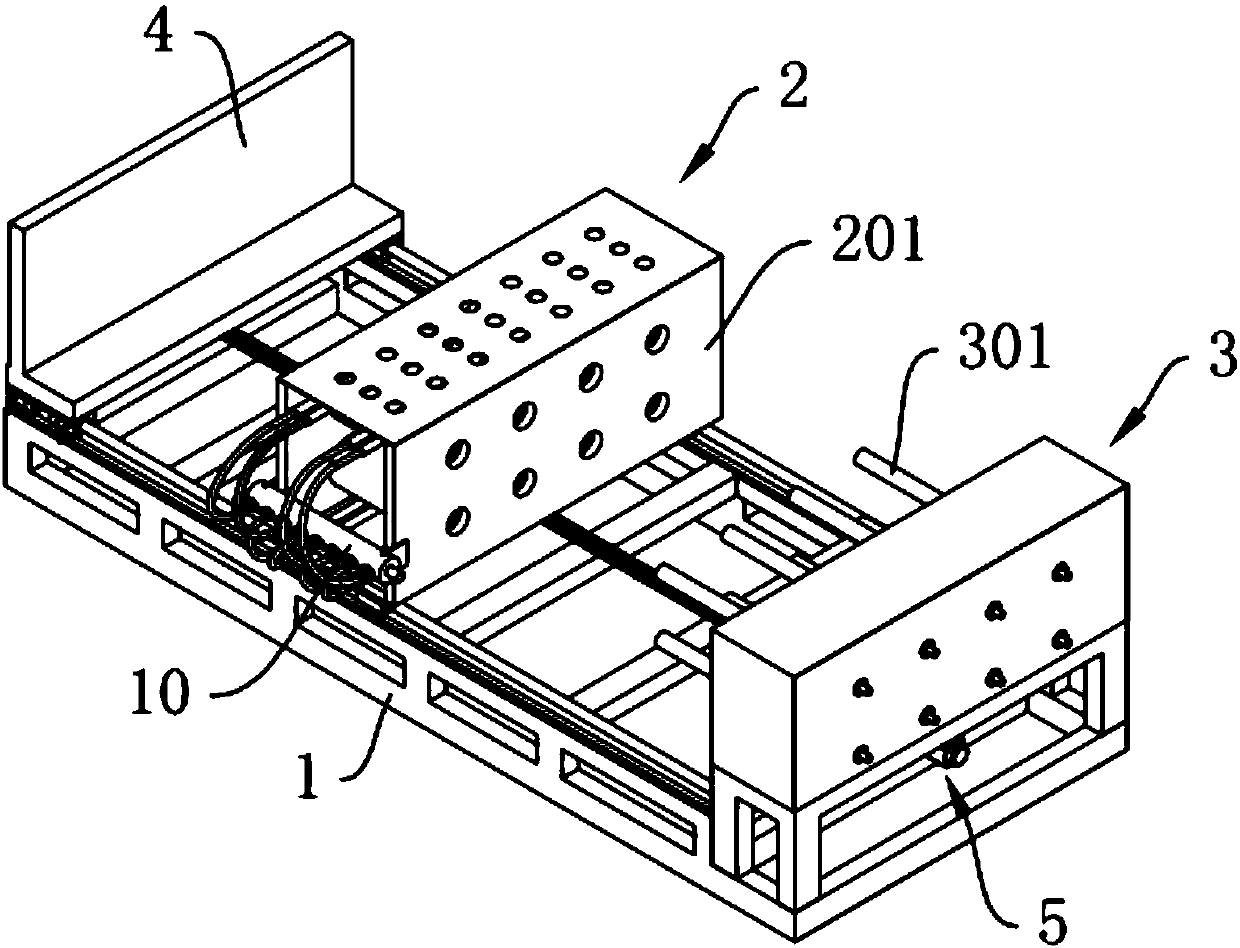
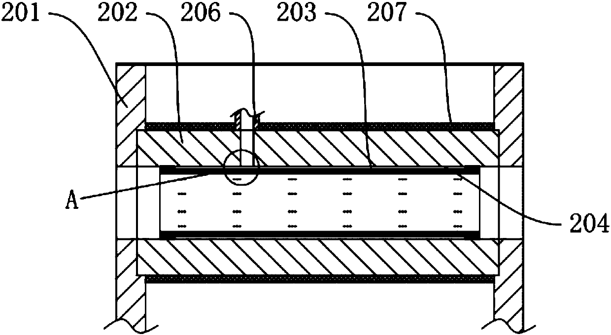
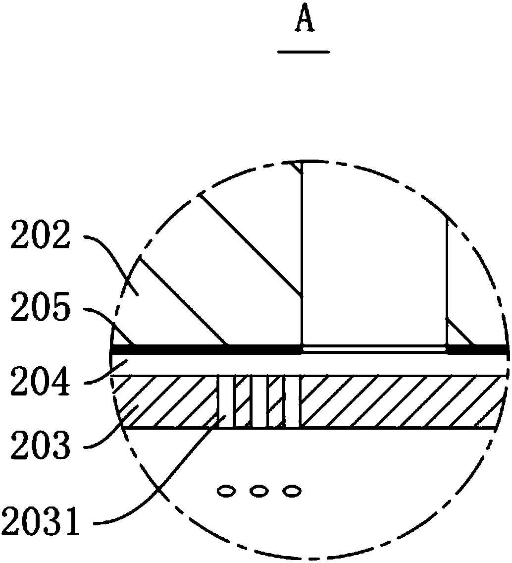
[0036] see figure 1 , a heat-shrinkable tubing machine, comprising a frame 1, a heating device 2 is slidably connected to the frame 1, combined with figure 2 and 3 , the heating device 2 includes a heating rack 201, and 8 heating cylinder assemblies are arranged in an array in the heating rack 201. The heating cylinder assembly includes a heating cylinder 202 fixedly installed on the heating rack 201, and a heat conducting cylinder 203 is pierced in the heating cylinder 202, and the heat conducting cylinder 203 is made of high thermal conductivity material. In this embodiment, the heat conduction cylinder 203 is made of copper. There is a ring groove on the outer wall of the middle part of the heat conduction cylinder 203. A heating chamber 204 is formed between the heat conduction cylinder 202 and the heat conduction cylinder 203. In the heat conduction cylinder 202 An electric heater 205 is attached to the inner wall of the heating chamber 204. The electric heater 205 is s...

Embodiment 2

[0042] see Figure 5 , a heat-shrinkable tubing machine. The difference between this embodiment and Embodiment 1 is that the fixed rod 301 is rotatably connected to the fixed frame 302, and the fixed frame 302 is fixed with a rotating motor 303 inside. The connection between the rotating motor 303 and the fixed rod 301 The connection between them is driven by a sprocket 304 and a chain 305. The fixed rod 301 adopts an air expansion shaft, and the air inlet end of the fixed rod 301 is connected with an air compressor. The thermal insulation layer 207 provided on the outer wall of the heating cylinder 202 is formed by uniform coating of thermal insulation paint, specifically adopting model ZS-211 reflective thermal insulation paint.

[0043] In actual operation, after the pipe covered with the heat-shrinkable tube to be heated is placed on the fixed rod 301, the fixed rod 301 can completely fix the pipe after being ventilated. When the heat-shrinkable tube is heated in the heati...


PUM

PropertyMeasurementUnit
thermal conductivityaaaaaaaaaa

Abstract

The invention discloses a heat shrinkage pipe wrapping machine. A rack is included and is in sliding connection with a heating device. The part, on one side of the heating device, of the rack is provided with a pipeline fixing device. The heating device comprises a heating frame, and a plurality of heating barrel assemblies are arranged in the heating frame. Each heating barrel assembly comprisesa heating barrel fixedly arranged on the heating frame, wherein a heat conduction barrel penetrates through the heating barrel, a heating cavity is reserved between the heating barrel and the heat conduction barrel, and an electric heater is arranged in the heating cavity. The heating frame is driven by a power device. The pipeline fixing device is provided with fixing rods opposite to the heatingbarrel assemblies. The whole machine operation is simple, each worker can conduct heating work on a plurality of pipeline exterior heat shrinkage pipes at a time, the labor cost and the labor intensity are reduced, the work efficiency is improved, the quality of protection layers formed after heat shrinkage pipe contraction is guaranteed, and social progress is promoted.

Description

technical field [0001] The invention relates to the technical field of automation equipment, in particular to a heat-shrinkable tube wrapping machine for heating a heat-shrinkable tube on a pipeline. Background technique [0002] In the oil and gas industry for long-distance transportation of oil, natural gas steel pipes, urban gas pipe networks, heating steel pipes, and tap water pipes, the welded parts are susceptible to corrosion. In some composite pipe connections, it is necessary to uncover the anticorrosion layer on the surface of the composite pipe, so as to weld or connect the inner pipe. This requires anti-corrosion treatment of welded parts or exposed inner pipes. [0003] Existing pipe manufacturers will protect the heat-shrinkable tubes on the pipe jackets, but this process is done manually. The workers first put the heat-shrinkable tubes on the pipes, and then manually hold the heat-shrinkable tubes or flame guns on them. The heat-shrinkable tube is heated, so...

Claims


Application Information

Patent Timeline
Patent Type & Authority Applications(China)
IPC IPC(8): B29C65/66B29C65/78B29L23/00
CPCB29C65/66B29C65/7841B29C66/52272B29L2023/00
Inventor 孙志强
Owner NINGBO HENGYUAN PRECISION VALVES TECH
Why Eureka
Try Eureka