
Precision grinding machine guide rail

A precision grinding machine and guide rail technology, which is applied in the direction of grinding bed, grinding frame, grinding slide plate, etc., can solve the problems of shortening the service life of the guide rail, friction and wear of the guide rail and the chute, and affecting the grinding accuracy of the workpiece. Improve the service life, maintain the accuracy of use, and reduce friction

Pending Publication Date: 2019-08-23
CHANGZHOU DESU MACHINERY
View PDF0 Cites 0 Cited by
  • Summary
  • Abstract
  • Description
  • Claims
  • Application Information

AI Technical Summary

Problems solved by technology

In the traditional grinding machine structure, the guide rail in the track is usually set on the bottom surface of the worktable, and the two rails, one flat rail and one sharp rail, are used to cooperate to realize the movement of the worktable. The friction between the guide rail on the worktable and the chute fixed on the base is relatively large, and the guide rail and the chute are prone to friction and wear, which affects the grinding accuracy of the workpiece and shortens the service life of the guide rail

Method used


Image

  • Precision grinding machine guide rail
  • Precision grinding machine guide rail

Examples


Embodiment Construction

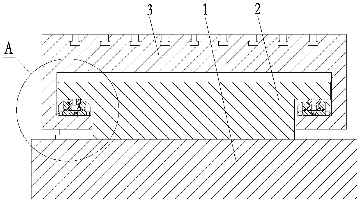
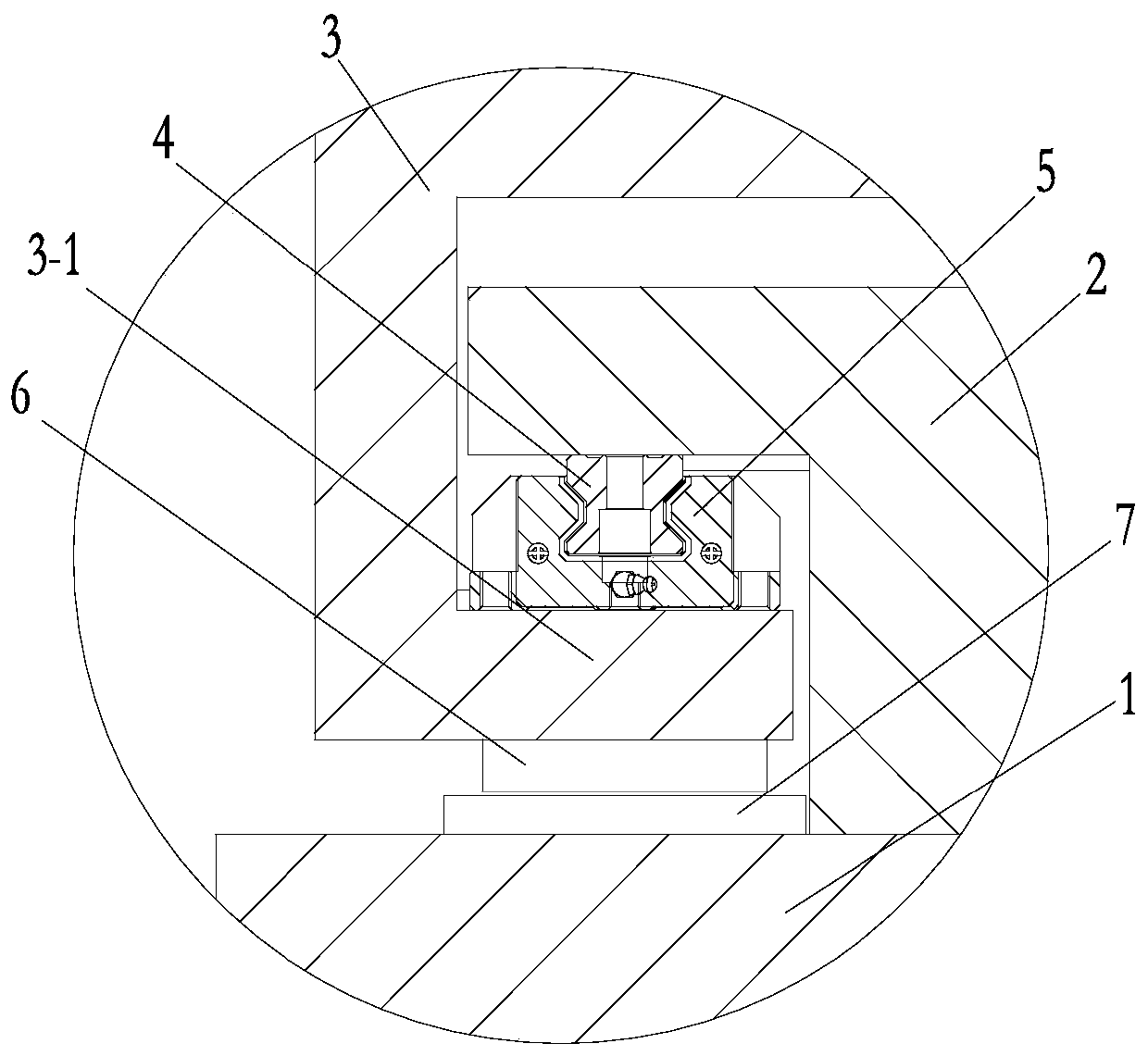
[0012] The present invention is described in further detail now in conjunction with accompanying drawing. These drawings are all simplified schematic diagrams, which only illustrate the basic structure of the present invention in a schematic manner, so they only show the configurations related to the present invention.

[0013] Such as figure 1 , figure 2 The guide rail of a precision grinding machine shown includes a base 1 as the foundation of the grinding machine, a worktable 3 is arranged above the base 1, and a T-shaped sliding table 2 is built inside under the working table 3, and the T-shaped sliding table 2 is fixed on the base. On the seat 1, the workbench 3 is slidably matched with the T-shaped slide table 2, and the upper surface of the workbench 3 is provided with a T-shaped groove for fixing the workpiece.

[0014] Located between the bottom of the workbench 3 and the base 1 is a suspension mechanism that generates an upward suspension thrust to support the wor...


PUM


Abstract

The invention relates to a precision grinding machine guide rail. The precision grinding machine guide rail comprises a base, a worktable arranged above the base and a T-shaped sliding table embeddedin the worktable and fixed on the base, wherein the worktable is slidably matched with the T-shaped sliding table; and a suspension mechanism capable of generating the upward suspension thrust force to support the worktable when the worktable moves along the T-aped sliding table is arranged between the bearing bottom of the worktable and the base. The precision grinding machine guide rail utilizesthe reverse magnetic repulsion action between a coil and a magnetite slab to form the upward suspension driving force and the thrust force to overcome the weight of the worktable and a workpiece, sothat the guide rail only needs to provide guidance without bearing, and the friction force on the guide rail is very small, therefore, the use accuracy of the guide rail is maintained for a long time,and the service life of the guide rail is prolonged.

Description

technical field [0001] The invention relates to the technical field of mechanical equipment, in particular to a precision grinding machine guide rail. Background technique [0002] During the working process of the grinding machine, the workpiece is placed on the worktable, and the grinding process is completed by moving the worktable along the track, and the straightness and flatness of the processed workpiece are ensured by the action of the track. In the traditional grinding machine structure, the guide rail in the track is usually set on the bottom surface of the worktable, and the two rails, one flat rail and one sharp rail, are used to cooperate to realize the movement of the worktable. The friction between the guide rail on the worktable and the chute fixed on the base is relatively large, and the guide rail and the chute are prone to friction and wear, which affects the grinding accuracy of the workpiece and shortens the service life of the guide rail. Contents of ...

Claims


Application Information

Patent Timeline
IPC IPC(8): B24B41/02
CPCB24B41/02
Inventor 彭子平
Owner CHANGZHOU DESU MACHINERY
Learn More