Full-automatic tapping machine
A tapping machine, fully automatic technology, applied in the direction of driving devices, maintenance and safety accessories, metal processing machinery parts, etc., can solve the problems of limited precision, troublesome operation, inconvenience, etc., to achieve improved precision, simple structure, and convenient installation Effect
- Summary
- Abstract
- Description
- Claims
- Application Information
AI Technical Summary
Problems solved by technology
Method used
Image
Examples
Embodiment 1
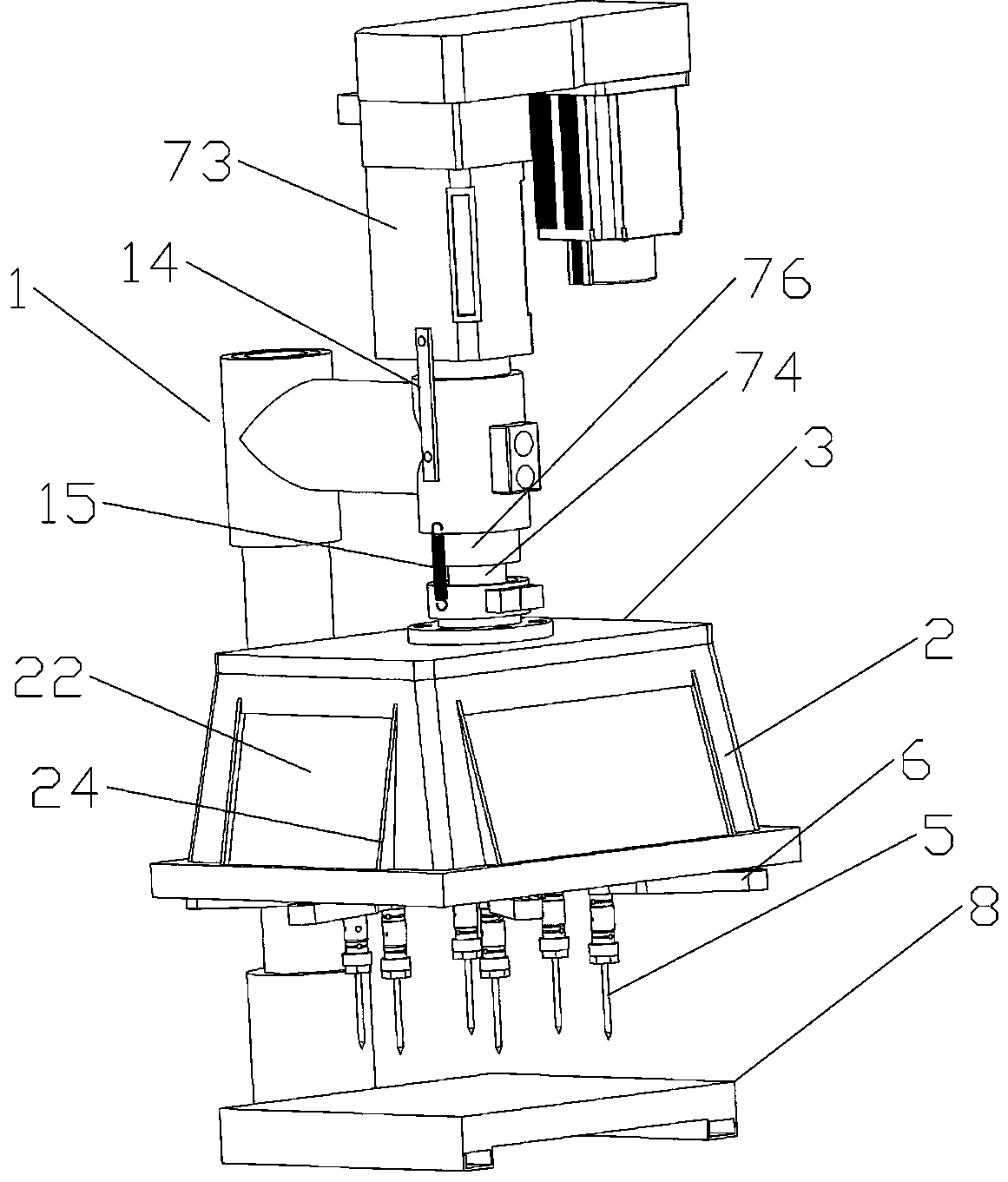
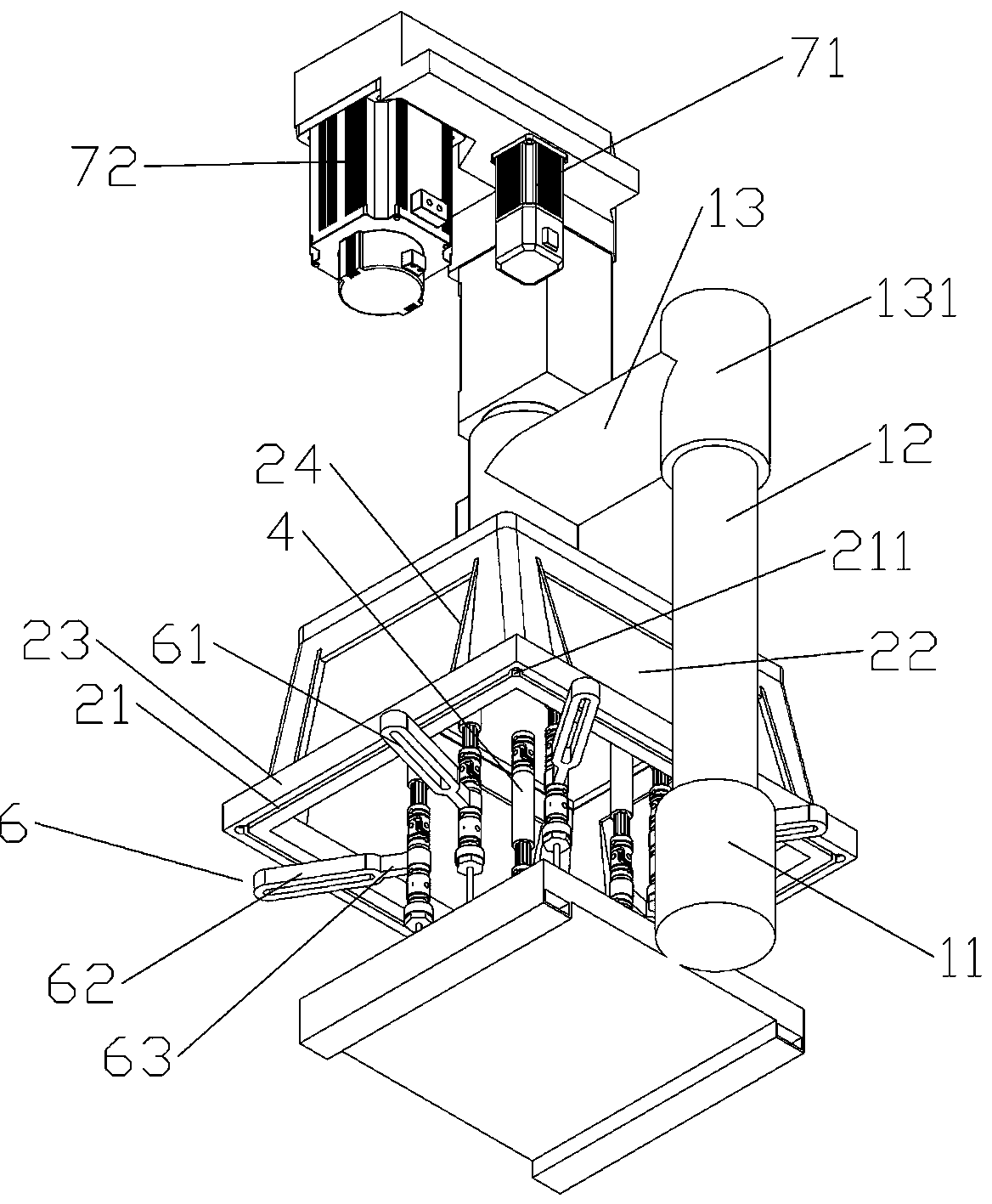
[0026] A fully automatic tapping machine, comprising a bracket 1, a lifting and rotating power mechanism arranged on the bracket, a tapping case cover mechanism suspended under the lifting and rotating power mechanism, and a workpiece mounting platform 8 located below the tapping case cover mechanism; The tapping box cover mechanism includes a box cover body 2 with a gear box 3 connected to the lifting and rotating power mechanism on the top, and a plurality of universal joints that are arranged on the top of the box cover body and penetrate into the gear box to connect with the gear transmission in the gear box. A shaft device 4, a drill bit 5 connected to the bottom end of the universal coupling, and a fastener 6 connected between the universal coupling and the case cover for fixing and adjusting the position of the drill bit, the bottom of the case cover An adjustment structure for connecting fasteners is provided on the rim. The adjustment structure is an adjustment channe...
Embodiment 2
[0028] The difference from the above embodiment is that the box cover is a square cover, the top of the square cover is a gear box, the surrounding walls are provided with transparent panels 22, and the bottom is a square wide bottom plate edge 23 for opening adjustment channels. , the outer edge of the wide bottom plate exceeds the bottom edge of the surrounding walls, and an external connecting rib 24 is provided between the outer surface of the surrounding wall and the edge of the wide bottom plate; the adjustment channel on the four sides of the wide bottom plate The end to end connection is connected, and an introduction port is provided on the corners where the adjustment channels on the four sides meet, and the connecting parts are bolt parts. The arrangement of the above-mentioned structure is convenient for the disassembly and assembly of the fasteners, and it is convenient for the staff to observe the tapping situation, and the cooperation of the various structural co...
Embodiment 3
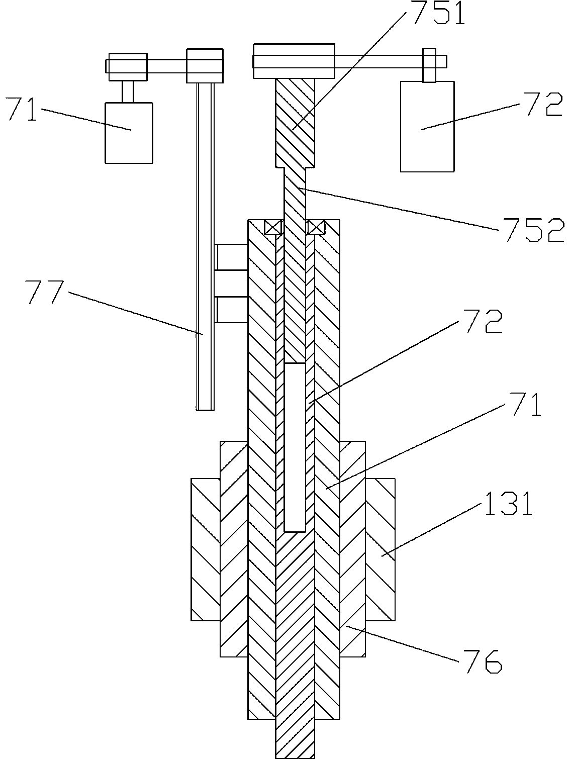
[0030] The difference from the above-mentioned embodiment is that the lifting and rotating power mechanism includes a lifting motor 71 for controlling the lifting of the box cover, a rotating motor 72 for controlling the rotation speed of the drill bit, a transmission box 73 connecting the lifting motor and the rotating motor, and a piercing motor. The lifting shaft 74 and the rotating main shaft 75 in the transmission box, the lower end of the lifting shaft is connected to the top of the box cover, and the lower end of the rotating main shaft penetrates into the gear box and is connected with the gears in the gear box. The lifting motor and the rotating motor adopt feeding motors.
[0031]The rotating main shaft is passed through the lifting shaft, and the lifting shaft is covered with a guide sleeve 76 whose upper end is connected to the transmission box. The guide sleeve is detachably connected with the bracket, and the lifting shaft is located at Parts inside the transmiss...
PUM
 Abstract
Description
Claims
Application Information
 - R&D Engineer
- R&D Manager
- IP Professional
- Industry Leading Data Capabilities
- Powerful AI technology
- Patent DNA Extraction
Browse by: Latest US Patents, China's latest patents, Technical Efficacy Thesaurus, Application Domain, Technology Topic, Popular Technical Reports.
© 2024 PatSnap. All rights reserved.Legal|Privacy policy|Modern Slavery Act Transparency Statement|Sitemap|About US| Contact US: help@patsnap.com


