
Deep-cone thickening sand bin with fluidized sand discharging device

A deep cone thickening and chemical device technology, which is applied to the feeding/discharging device of the settling tank, chemical instruments and methods, settling tank, etc. , interfere with tailings thickening rate and other issues, to achieve the effect of maintenance-free power consumption, wide applicability and simple structure

Pending Publication Date: 2019-08-23
金诚信矿山工程设计院有限公司
View PDF0 Cites 4 Cited by
  • Summary
  • Abstract
  • Description
  • Claims
  • Application Information

AI Technical Summary

Problems solved by technology

These kinds of fluidized pulping methods have many disadvantages: the scraper rake type thickener has complex structure, high manufacturing cost, high power consumption, and there is still a hidden danger of rake pressure during operation; local fluidization of high-pressure water nozzles causes Slurry will reduce the concentration of discharged tailings and affect the concentration effect; pneumatic pulping will interfere with the natural settlement effect of tailings due to the rise of air bubbles, reducing the thickening rate; air-water linkage slurrying will also reduce the concentration of discharged tailings and the adverse consequences of interfering with the natural settlement of tailings and reducing the thickening rate

Method used


Image

  • Deep-cone thickening sand bin with fluidized sand discharging device
  • Deep-cone thickening sand bin with fluidized sand discharging device
  • Deep-cone thickening sand bin with fluidized sand discharging device

Examples


Embodiment Construction

[0041] The principles and features of the present invention are described below, and the examples given are only used to explain the present invention, and are not intended to limit the scope of the present invention.

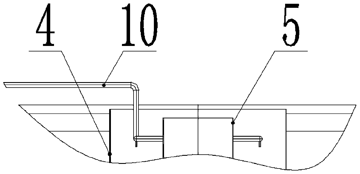
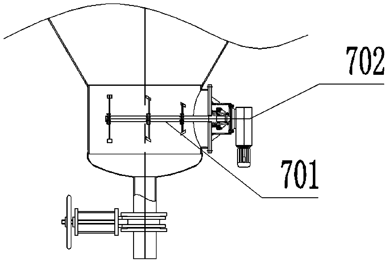
[0042] Such as Figure 1-Figure 5As shown, a deep cone dense sand bin with a fluidized sand release device includes a sand bin body 1, a feed pipe 2, an overflow tank 3, a feed well 4, a circulation well 5, an annular diversion cone 6, a stirring The fluidization device 7 and the flocculant inlet pipe 10; the overflow tank 3 is fixedly connected to the top of the inner wall of the sand bin body 1, and the overflow tank 3 communicates with the supernatant return pipe 9; The feed well 4 is set in the top center of the cavity of the sand bin body 1 and is fixedly connected with the sand bin body 1; the circulation well 5 is set in the feed well 4 and connected with the feed well 4. The top of the feed well 4 is fixedly connected by a steel structure support, and ...


PUM

PropertyMeasurementUnit
angleaaaaaaaaaa

Abstract

The invention relates to a deep-cone thickening sand bin with a fluidized sand discharging device. The deep-cone thickening sand bin with a fluidized sand discharging device comprises a sand bin body,a material feeding pipe, a flocculant inlet pipe, an overflow tank, a material feeding well, a circulation well, an annular guide cone and a stirring fluidization device, wherein the overflow tank isfixedly connected to the top of the inner wall of the sand bin body, and communicates with a supernatant return pipe, the material feeding well is disposed at the center of the top of the sand bin body, and is fixedly connected with the sand bin body, and the circulation well is disposed in the material feeding well, and is fixedly connected with the material feeding well; a material feeding zoneis formed between the material feeding well and the circulation well, the material feeding pipe communicates with the material feeding zone, and the annular guide cone is disposed directly below thecirculation well, and is fixedly connected with the inner wall of the sand bin body; and the diameter of the top of the annular guide cone is the same as the diameter of the circulation well, a material outlet is formed in the bottom of the sand bin body, and the stirring fluidization device is fixedly connected with the mouth outlet. A special flow field is formed after tailings is introduced into the sand bin, no consumption of waterpower and gas power is generated, the fluidization effect is good, and it is ensured that the mortar concentration and the thickening effect are not reduced.

Description

technical field [0001] The invention relates to the technical field of mine environmental protection equipment, in particular to a deep cone dense sand bin with a fluidized sand discharge device. Background technique [0002] When the mining industry concentrates and dehydrates the low-concentration tailings produced in the beneficiation process, it generally uses a thickener or a vertical sand bin. Most of the thickeners in the prior art are rake-type unloading, which have problems such as large area, complex structure, high power consumption, low concentration efficiency, and complicated maintenance. For high-density tailings that settle at the lower part of the thickener, There is also the danger of crushing the rake. [0003] At the bottom of the thickener or vertical sand bin, when the particle concentration reaches a certain value, the rheological characteristics of the slurry are non-Newtonian fluid characteristics, and its yield stress is relatively large, making it...

Claims


Application Information

Patent Timeline
Patent Type & Authority Applications(China)
IPC IPC(8): B01D21/00B01D21/01B01D21/02B01D21/24B01D21/26
CPCB01D21/0087B01D21/2411B01D21/265B01D21/262B01D21/2405B01D21/01B01D21/02B01D21/245B01D21/0042B01D21/2472
Inventor 吴学民于云龙马波赵占斌张斌王国立
Owner 金诚信矿山工程设计院有限公司
Learn More