Real-time positioning method and device applied to automatic driving
A technology of automatic driving and real-time positioning, which can be applied to measurement devices, use re-radiation, and re-radiation of electromagnetic waves. It can solve problems such as poor positioning accuracy, long data processing time, and processing time.
- Summary
- Abstract
- Description
- Claims
- Application Information
AI Technical Summary
Problems solved by technology
Method used
Image

Examples
Embodiment 1
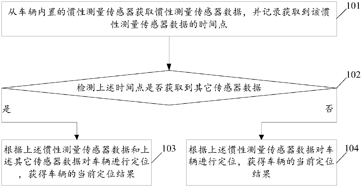
[0081] see figure 1 , figure 1 It is a schematic flowchart of a real-time positioning method applied to automatic driving disclosed in an embodiment of the present invention. like figure 1 As shown, the real-time positioning method applied to automatic driving may include the following steps:
[0082] 101. Acquire inertial measurement sensor data from an inertial measurement sensor built in the vehicle, and record the time point at which the inertial measurement sensor data is acquired.
[0083] In the embodiment of the present invention, the inertial measurement sensor (Inertial measurement unit, IMU) sends the collected inertial measurement sensor data to the data processor, and the data processor can record and obtain the inertial measurement sensor data when the inertial measurement sensor data is obtained. The time point of the data, and set the time stamp of the inertial measurement sensor data based on this time point. Similarly, when other sensors (image sensor, wh...
Embodiment 2
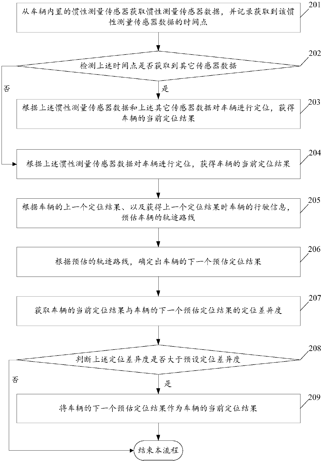
[0094] see figure 2 , figure 2 It is a schematic flowchart of another real-time positioning method applied to automatic driving disclosed in the embodiment of the present invention. like figure 2 As shown, the real-time positioning method applied to automatic driving may include the following steps:
[0095] For the detailed description of steps 201 to 204, please refer to the detailed description of steps 101 to 104 in Embodiment 1, which will not be repeated in this embodiment of the present invention. Wherein, after step 204 is executed, step 205 is executed.
[0096] 205. Estimate the trajectory of the vehicle according to the last positioning result of the vehicle and the driving information of the vehicle when the last positioning result was obtained.
[0097] 206. Determine the next estimated positioning result of the vehicle according to the estimated trajectory.
[0098] In the embodiment of the present invention, the above-mentioned driving information includ...
Embodiment 3
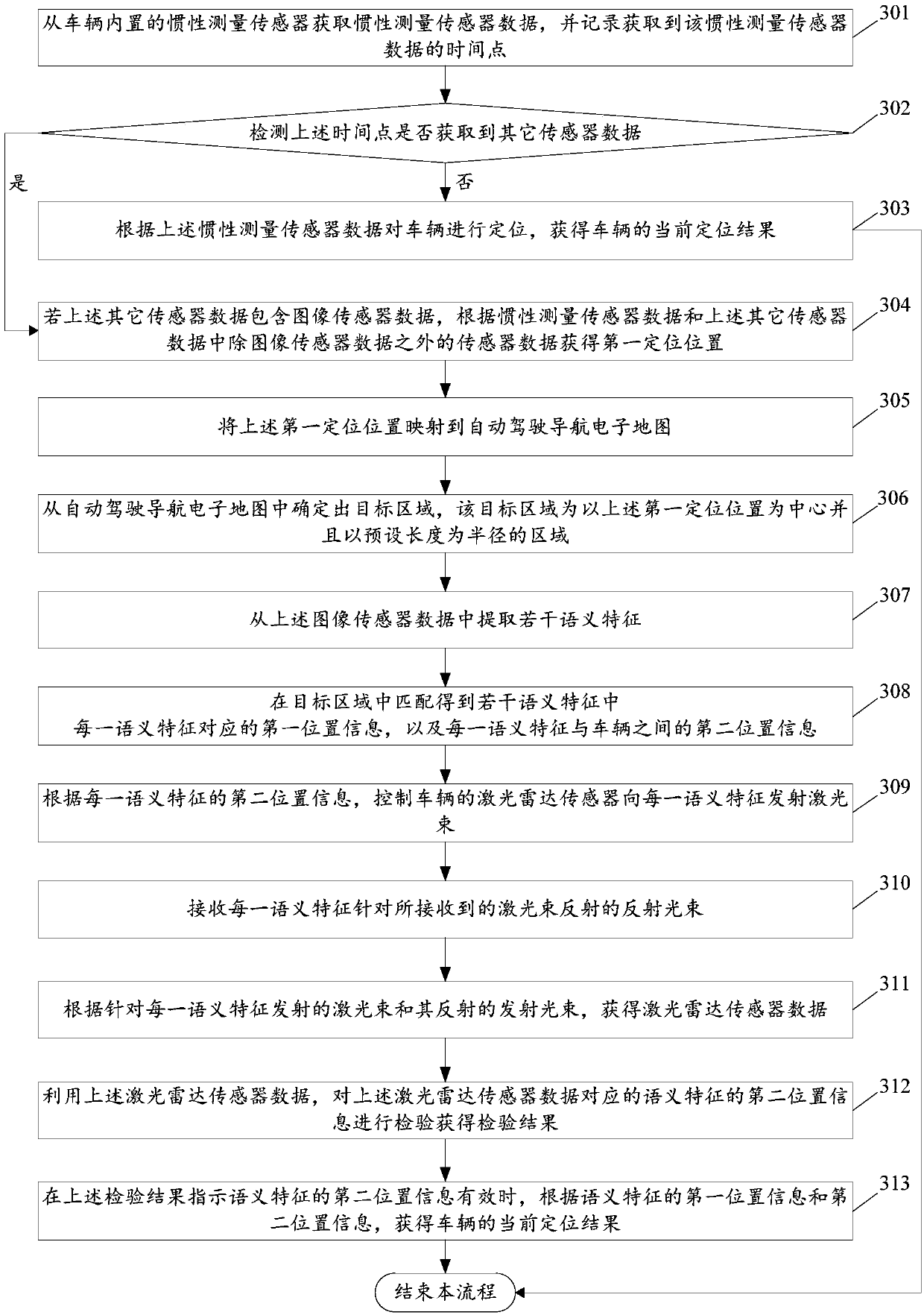
[0108] see image 3 , image 3 It is a schematic flowchart of another real-time positioning method applied to automatic driving disclosed in the embodiment of the present invention. like image 3 As shown, the real-time positioning method applied to automatic driving may include the following steps:
[0109] 301. Acquire inertial measurement sensor data from an inertial measurement sensor built in the vehicle, and record the time point at which the inertial measurement sensor data is acquired.
[0110] 302. Detect whether other sensor data is acquired at the above time point, if yes, perform step 304; if not, perform step 303.
[0111] 303. Position the vehicle according to the above inertial measurement sensor data, and obtain a current positioning result of the vehicle.
[0112] Wherein, for the detailed description of steps 301 to 303, please refer to the description in Embodiment 1, which will not be repeated in this embodiment of the present invention.
[0113] 304. ...
PUM
 Abstract
Description
Claims
Application Information
 - R&D
- Intellectual Property
- Life Sciences
- Materials
- Tech Scout
- Unparalleled Data Quality
- Higher Quality Content
- 60% Fewer Hallucinations
Browse by: Latest US Patents, China's latest patents, Technical Efficacy Thesaurus, Application Domain, Technology Topic, Popular Technical Reports.
© 2025 PatSnap. All rights reserved.Legal|Privacy policy|Modern Slavery Act Transparency Statement|Sitemap|About US| Contact US: help@patsnap.com