Engine pre-swirl system

A pre-rotation system and engine technology, applied in engine functions, engine components, machines/engines, etc., can solve the problems of poor cooling effect of airflow channels and difficult manufacturing, avoid flow separation, reduce manufacturing difficulty, reduce The effect of flow loss

Active Publication Date: 2021-07-30
AECC COMML AIRCRAFT ENGINE CO LTD
View PDF7 Cites 0 Cited by
  • Summary
  • Abstract
  • Description
  • Claims
  • Application Information

AI Technical Summary

Problems solved by technology

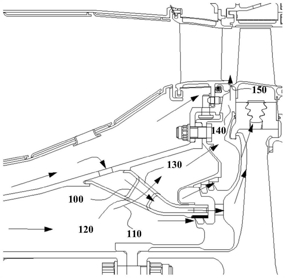
[0009] The technical problem to be solved by the present invention is to provide an engine pre-rotation system in order to overcome the disadvantages of poor cooling effect of the airflow channel of the pre-rotation system in the prior art and great manufacturing difficulty.

Method used


Image

  • Engine pre-swirl system
  • Engine pre-swirl system
  • Engine pre-swirl system

Examples


Embodiment 1

[0041] Figure 5 It is a schematic diagram of the first embodiment of the engine pre-swirl system of the present invention after being divided along the circumferential surface of revolution. Image 6 It is an axonometric view of the rotary plane in Embodiment 1 of the engine pre-swirl system of the present invention. Figure 7 It is a forward projection view of the outlet axial section of the rectifying vane in Embodiment 1 of the engine pre-swirl system of the present invention. Figure 8 It is a rear projection view of the axial section at the inlet of the downstream channel in Embodiment 1 of the engine pre-swirl system of the present invention.

[0042] like Figure 5 to Figure 8As shown, the present invention discloses a kind of engine pre-swirl system, the upstream of the pre-swirl nozzle 10 is provided with a plurality of rectifying blades 20, according to the needs of the original through-flow pillar to circulate cold air, the rectifying blades 20 are provided with ...

Embodiment 2

[0048] Figure 9 It is an axonometric view of the rotary plane in Embodiment 2 of the engine pre-swirl system of the present invention. like Figure 9 As shown, the structure of this embodiment is basically the same as that of Embodiment 1, and the difference is that a plurality of vane-shaped nozzle cascades 30 are arranged downstream of the rectifying vane 20 for rectifying the incoming flow, and the rectifying vane 20 and the nozzle The deflection directions of the cascades 30 are the same, and the airflow deflection angle ranges from 0° to 80°. A rectifying vane channel 40 is formed between two adjacent rectifying vanes 20 , and a nozzle channel 50 is formed between two adjacent nozzle cascades 30 . Preferably, the deflection angle of the air flow from the inlet of the rectifying blade 20 to the outlet of the nozzle cascade 30 is in the range of 70°-80°. The direction of the air outlet angle of the rectifying blade 20 deviates from the inlet angle of the blade of the no...


PUM


Abstract

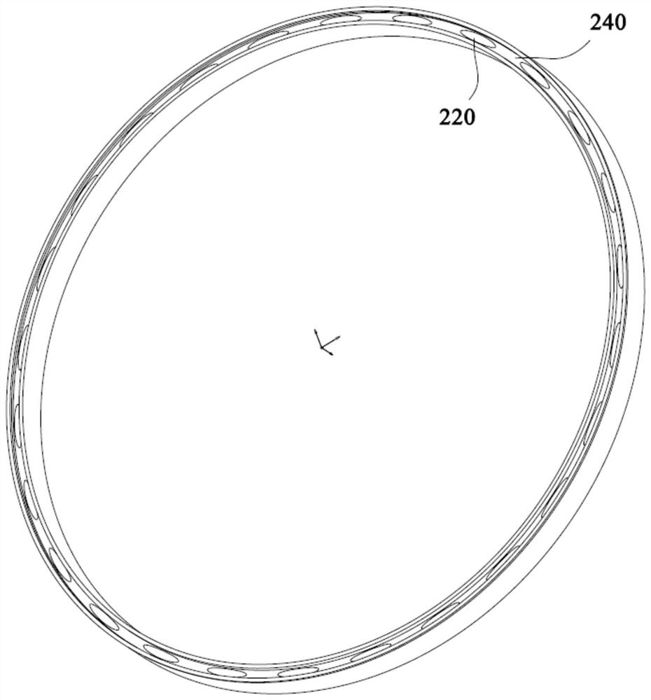
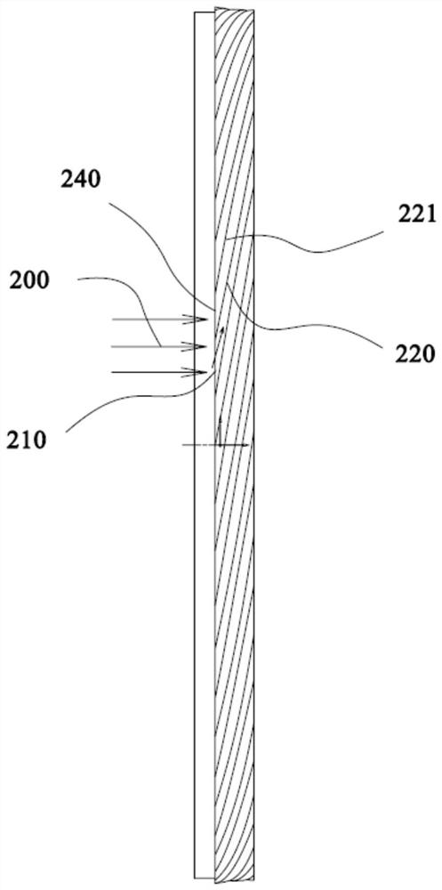
The present invention provides an engine pre-swirl system, wherein a plurality of rectifying vanes are arranged upstream of the pre-swirling nozzle of the pre-swirling system, vent holes are opened on the rectifying vanes, and the rectifying vanes are connected with the pre-swirling The inner and outer annular surfaces of the nozzle form a flow channel. The flow channel accelerates and deflects the incoming flow. The engine pre-swirling system of the present invention designs the vent hole of the front cylindrical shape of the pre-swirling system as a rectifying blade. Before the air flow enters the pre-swirling nozzle, the rectifying blade deflects it first. Flow loss, on the other hand, can effectively solve the problem that the airflow turning angle at the inlet of the existing straight round hole pre-rotation nozzle is too large. After being rectified by the rectifying blades, the angle of attack of the incoming flow at the inlet of the round-hole nozzle is reduced, which can prevent the flow separation of the airflow at the side facing away from the incoming flow.

Description

technical field [0001] The invention relates to the field of aero-engines, in particular to an engine pre-swirl system. Background technique [0002] With the continuous improvement of aero-engine performance, the gas temperature before the turbine gradually increases. The temperature before the turbine of the early turbojet engine is only 1000K-1200K. At present, the temperature in front of the turbine has reached 2100K, which poses a serious challenge to the material, process and cooling technology of the turbine components. Most of the existing materials cannot withstand such a high temperature for a long time, so the high-pressure turbine blades in a high-temperature and high-pressure environment need to be cooled by cooling air. However, the existing turbine blade cooling technology has obvious limitations, and its potential exploitation is close to the limit, which prompts people to turn more and more to tap the cooling potential by improving the characteristics of t...

Claims


Application Information

Patent Timeline
Patent Type & Authority Patents(China)
IPC IPC(8): F01D9/04
CPCF01D9/041F05D2260/14
Inventor 潘贤德范宜龙李蓓罗华玲吕剑波
Owner AECC COMML AIRCRAFT ENGINE CO LTD
Why Eureka
Try Eureka