Method and device thereof for shallow type drilling machine self-adaptive balance

An adaptive drilling rig technology, applied in support devices, automatic drilling control systems, earthwork drilling and production, etc., can solve problems such as unsuitable submersible drilling rigs, and achieve easy installation and maintenance, increased support range, and high-speed support positioning Effect

Active Publication Date: 2019-08-20
NANTONG UNIVERSITY
View PDF8 Cites 0 Cited by
  • Summary
  • Abstract
  • Description
  • Claims
  • Application Information

AI Technical Summary

Problems solved by technology

However, the above method is not suitable for submersible drilling rigs operating in narrow tunnels or mines, and special devices must be designed according to actual working conditions to realize the self-adaptive balance of the drilling rig

Method used


Image

  • Method and device thereof for shallow type drilling machine self-adaptive balance
  • Method and device thereof for shallow type drilling machine self-adaptive balance

Examples


Embodiment 1

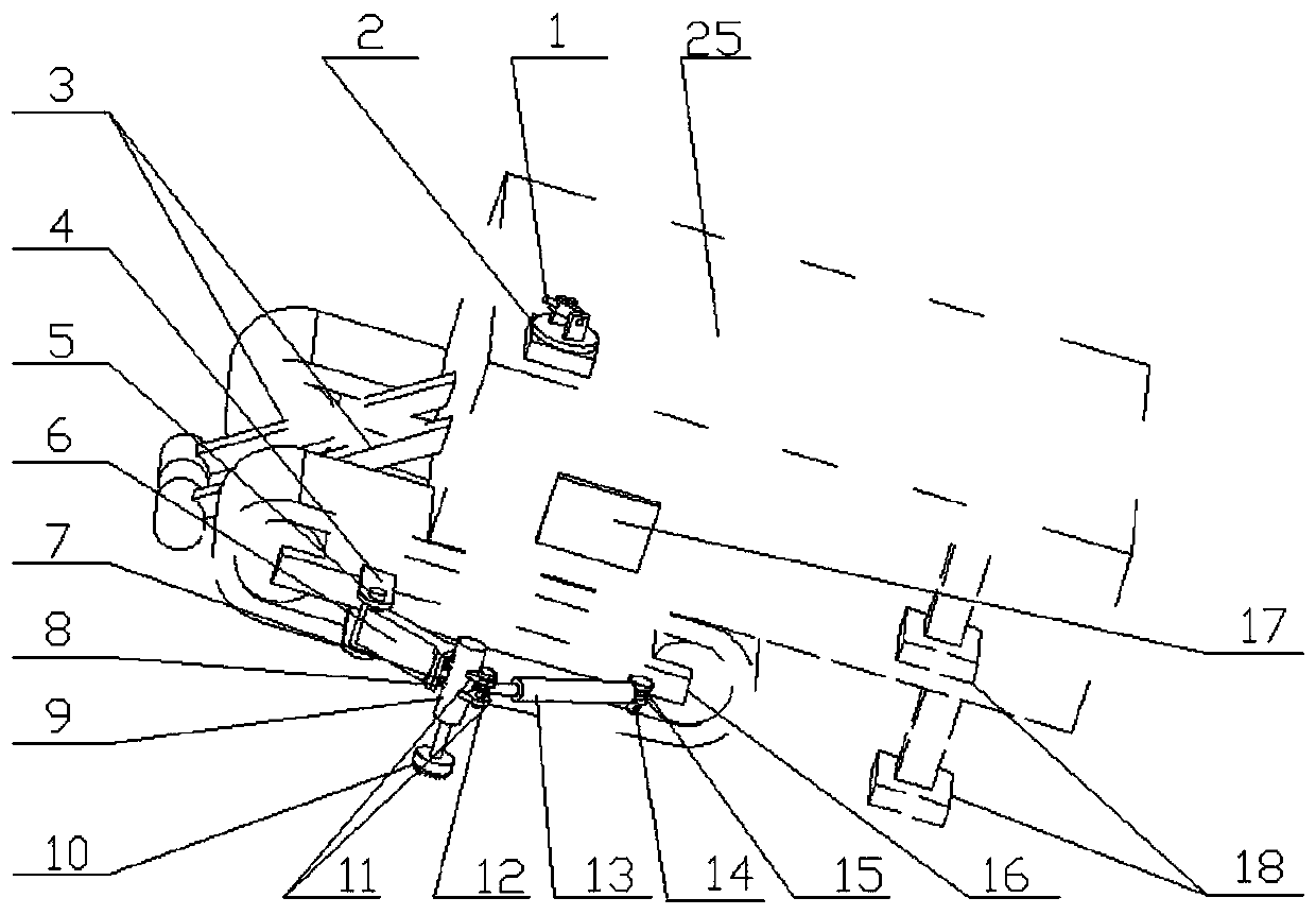
[0041] At first the drilling rig is advanced to the vicinity of the rock wall that needs to be drilled, and then the front support leg (3) and the rear support leg (18) of the initial support device are first supported on the ground. Then use the laser rangefinder (1) and the angular displacement sensor (2) to obtain real-time position information of the drilling face of the tunnel rock wall, for example, the measured distance is 1.5m, and the angle is 20°. The angle value γ can be obtained by the above algorithm is 27.5°. Look up table 3 and know that this angle is less than 30 °, so central controller (17) does not have drive signal output. The hydraulic pump does not work, so the supporting device remains in its original state. At this time, it is in the working state that does not need to start the self-adaptive balancing device.

Embodiment 2

[0043] At first the drilling rig is advanced to the vicinity of the rock wall that needs to be drilled, and then the front support leg (3) and the rear support leg (18) of the initial support device are first supported on the ground. Then use the laser range finder (1) and the angular displacement sensor (2) to obtain real-time position information of the tunnel rock wall drilling face, for example, the measured distance is 2.5m, the angle is 40°, and the angle value γ can be obtained by the above algorithm It is 52.5°, and it can be seen from Table 3 that the angle is in the range of 50°-60°, so there is a drive signal output. Specific steps are as follows:

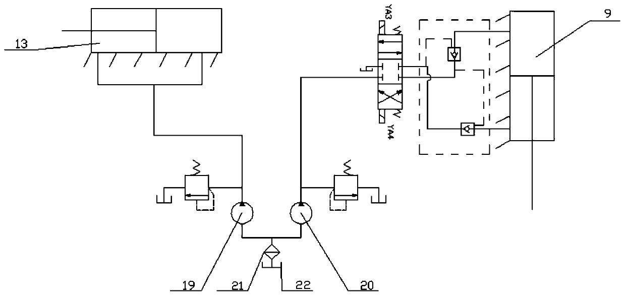
[0044] (1) The hydraulic pump works, first the central controller (17) drives the deflection oil cylinder (13) to extend 55cm from the extended end;

[0045] (2) After the working stroke of the deflection cylinder ends, the support cylinder (9) starts to work, so that the sawtooth support claw (10) supports the ground. ...

Embodiment 3

[0048] At first the drilling rig is advanced to the vicinity of the rock wall that needs to be drilled, and then the front support leg (3) and the rear support leg (18) of the initial support device are first supported on the ground. Then use the laser range finder (1) and the angular displacement sensor (2) to obtain real-time position information of the tunnel rock wall drilling face, for example, the measured distance is 4m, and the angle is 70°. The angle value γ obtained by the above algorithm is 90°, look up Table 3, it can be seen that the angle is in the range of more than 80°, so there is a drive signal output. The body steps are as follows:

[0049] (1) The hydraulic pump works, so at first the central controller (17) drives the deflection oil cylinder (13) overhanging end 100cm (reaching the maximum working stroke place).

[0050] (2) After the working stroke of the deflection cylinder ends, the support cylinder (9) starts to work, so that the sawtooth support claw...


PUM


Abstract

The invention discloses a method and device thereof for shallow type drilling machine self-adaptive balance. The method for shallow type drilling machine self-adaptive balance comprises the steps thata laser rangefinder and an angular displacement sensor are utilized to acquire position information of a tunnel rock wall drilling working face in real time; based on the position information, through calculation of the deflection angle and elongation distance of a drilling arm, deflection of the center of gravity of a drilling machine is determined; and adjustable balance supporting devices on the left side and the right side of the drilling machine are pertinently controlled to rotate correspondingly, the supporting range is increased, and self-adaptive balance of the drilling machine in the working process is achieved. The device comprises the laser rangefinder, the angular displacement sensor, a supporting oil cylinder, a deflection oil cylinder, a supporting transverse beam, a central controller and an oil way control circulating system. The deflection oil cylinder does extending and contracting and rotary motions, and the supporting oil cylinder is driven to rotate correspondingly. According to the method and device thereof for shallow type drilling machine self-adaptive balance, working face signals detected are utilized to control changes of the supporting manner of the drilling machine so that the supporting manner can be adjusted self-adaptively by the supporting devices along with changes of the working face; real-time balanced location of the shallow type drillingmachine in a narrow and long tunnel is achieved; and the working range of the shallow type drilling machine is expanded.

Description

technical field [0001] The invention relates to a method and a device for self-adaptive balancing of a submersible drilling rig, in particular to a method and a device for realizing self-adaptive balancing based on a balance support device facing narrow tunnels or mine working faces. Background technique [0002] Down-the-hole drilling rigs usually work in narrow tunnels or for drilling and grouting at the bottom of mines, and the working space at the bottom is narrow and the visibility is poor. In addition, some perforated rock walls are not vertical surfaces, but slopes with a certain angle. When the drilling rig is working at the limit position, it is easy to lose balance. [0003] Generally, the support of the drilling rig is to maintain the balance of the whole machine during operation through four support legs symmetrically arranged in front, rear, left and right of the drilling machine body, but this support method can only meet the two-two connection between the proj...

Claims


Application Information

Patent Timeline
Patent Type & Authority Applications(China)
IPC IPC(8): E21B44/00E21B15/00
CPCE21B44/00E21B15/00
Inventor 张华朱钱威房佳恒
Owner NANTONG UNIVERSITY
Why Eureka
Try Eureka