
Positioning mechanism for adjustable type upper ornamental plate hot riveting machine for new energy automobile

A new energy vehicle and positioning mechanism technology, applied in mechanical equipment, vibration suppression adjustment, spring/shock absorber, etc., can solve problems such as inability to adjust hot riveting machines, achieve not easy to shake off, strong adaptability, improve stability and safety effect

Active Publication Date: 2019-08-20
广东富强科技股份有限公司
View PDF3 Cites 1 Cited by
  • Summary
  • Abstract
  • Description
  • Claims
  • Application Information

AI Technical Summary

Problems solved by technology

[0005] The purpose of the present invention is to provide a positioning mechanism for an adjustable hot riveting machine for upper decorative panels for new energy vehicles, which can solve the problem that the existing positioning mechanism cannot be quickly adjusted according to hot riveting machines of different sizes, and when faced with different sizes The hot riveting machine and different types of hot riveting machines need to replace the positioning mechanism

Method used


Image

  • Positioning mechanism for adjustable type upper ornamental plate hot riveting machine for new energy automobile
  • Positioning mechanism for adjustable type upper ornamental plate hot riveting machine for new energy automobile
  • Positioning mechanism for adjustable type upper ornamental plate hot riveting machine for new energy automobile

Examples


Embodiment Construction

[0042] The technical solutions of the present invention will be clearly and completely described below in conjunction with the embodiments. Apparently, the described embodiments are only some of the embodiments of the present invention, not all of them. Based on the embodiments of the present invention, all other embodiments obtained by persons of ordinary skill in the art without creative efforts fall within the protection scope of the present invention.

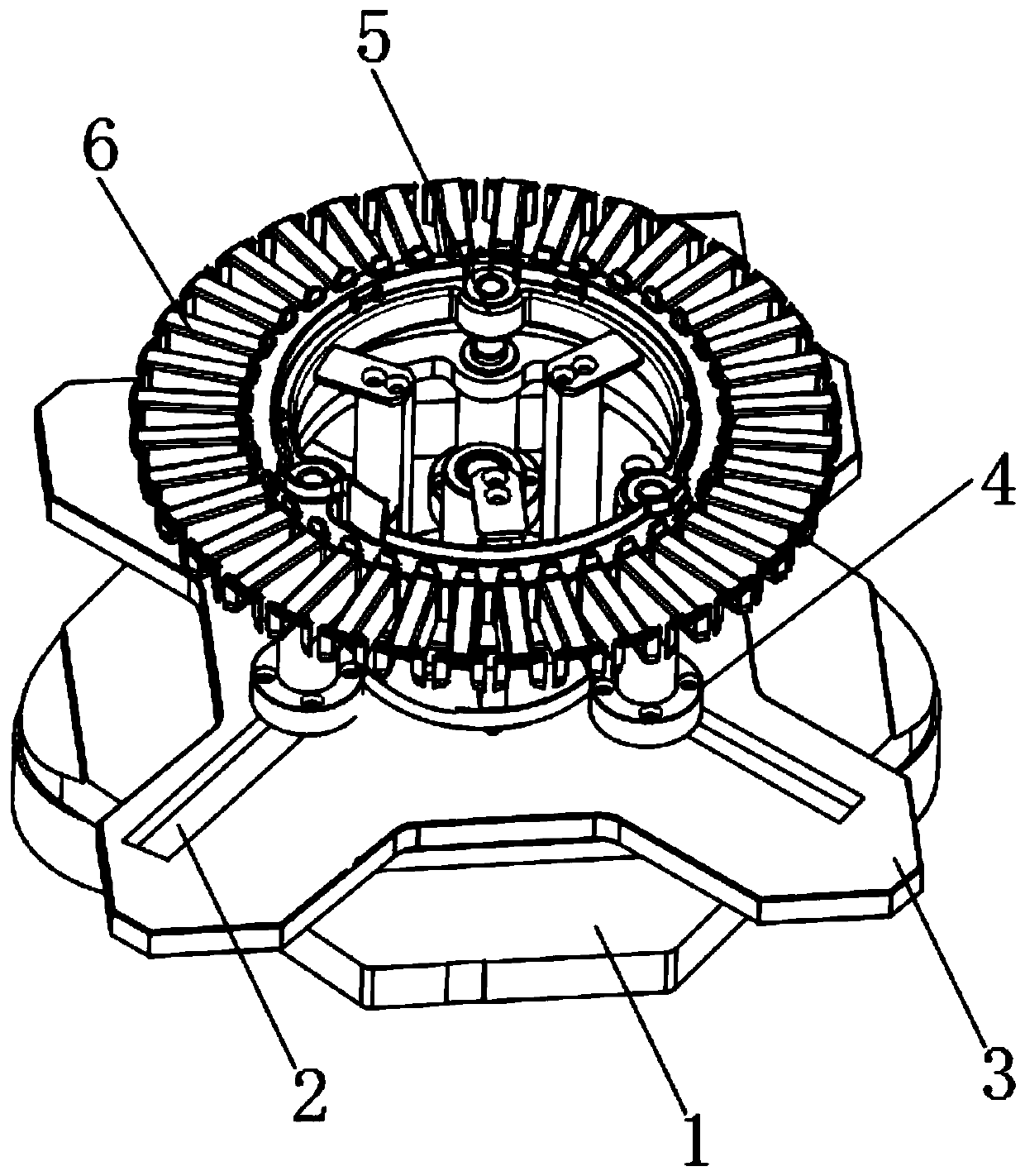
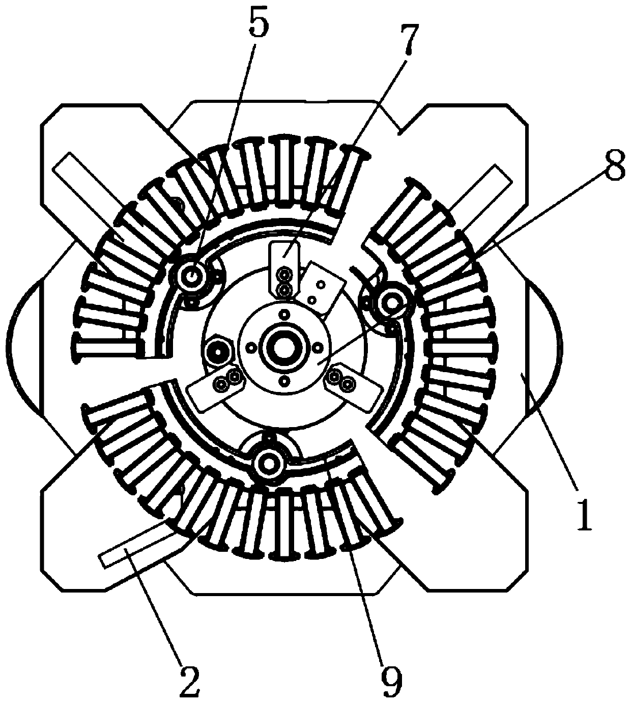
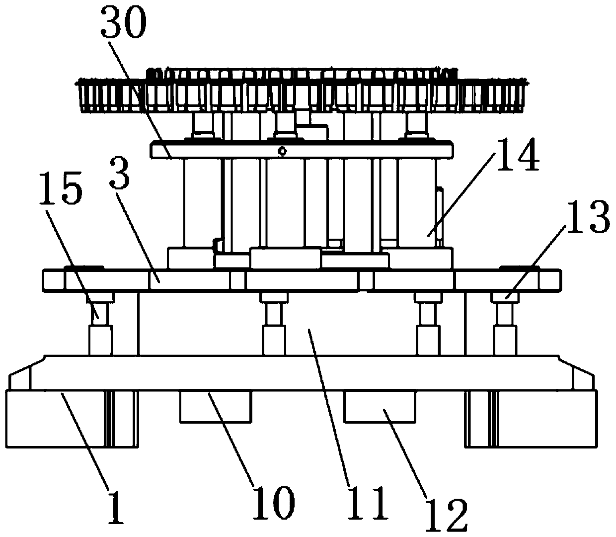
[0043] see Figure 1-10 As shown, a positioning mechanism for an adjustable hot riveting machine for upper trim for new energy vehicles, including a base 1, a support plate 3 and a mounting plate 9, the support plate 3 is horizontally installed on the upper part of the base 1, and the bottom of the support plate 3 A rotating shaft 11 is installed between the middle end and the top middle end of the base 1, and the top of the base 1 is connected with several vertically arranged second hydraulic columns 15 around the rotating...


PUM


Abstract

The invention discloses a positioning mechanism for an adjustable type upper ornamental plate hot riveting machine for a new energy automobile. The positioning mechanism comprises a base, a supportingplate and a mounting plate; the supporting plate is horizontally mounted at the upper part of the base; a rotating shaft is mounted between the middle end of the bottom of the supporting plate and the middle end of the top of the base; a plurality of second hydraulic posts which are arranged vertically are connected to the periphery of the rotating shaft at the top of the base; and the top of each second hydraulic post is connected with a friction block. The top of the supporting plate is connected with a plurality of groups of first hydraulic posts; the tops of the first hydraulic posts areconnected with a mounting plate through connecting heads; and the outer side of the mounting plate is connected with a plurality of clamp groups. The space between a limiting plate and an adjusting plate is filled so that the interior is fuller; the stress area is increased; an inflating air bag can achieve the effects of buffering and shock-absorbing during shaking or after shaking in use, and the shaking force in the use can be reduced, so that a hot riveting machine can weld an automobile decorating plate stably in use; and the precision is higher.

Description

technical field [0001] The invention relates to a positioning mechanism, in particular to a positioning mechanism for an adjustable upper trim hot riveting machine for a new energy vehicle, belonging to the application field of hot riveting machines. Background technique [0002] The hot riveting machine generally adopts a pressing plate structure. The heat of the heating plate is transferred to the hot riveting head by electric heating. The hot riveting head heats the riveting column to melt it, and then blows it to cool and solidify to form the riveting head and fix the product. The hot riveting machine is usually fixed by a positioning mechanism during use. [0003] The Chinese patent with the application number 201610404275.0 discloses a fixture and its positioning mechanism, including a base, a first cylinder, a second cylinder, an air inlet pipe and an air outlet pipe. The positioning mechanism includes a positioning body, a first spring, a first positioning column and...

Claims


Application Information

Patent Timeline
Patent Type & Authority Applications(China)
IPC IPC(8): B29C65/02F16F15/023
CPCB29C65/02B29C66/80F16F15/023
Inventor 邓伟勇
Owner 广东富强科技股份有限公司
Learn More