Solar charger control circuit and solar charger

A solar charger and control circuit technology, applied in battery circuit devices, current collectors, circuit devices, etc., can solve problems such as the failure of the single-chip microcomputer to operate normally, the low utilization rate of solar energy, and the pull-down of the solar panel.

Pending Publication Date: 2019-08-16
深圳市辉曜科技有限公司
View PDF0 Cites 1 Cited by
  • Summary
  • Abstract
  • Description
  • Claims
  • Application Information

AI Technical Summary

Problems solved by technology

[0005] (1) The utilization rate of solar energy is not high, that is, the maximum power output cannot be achieved in many cases;
[0006] (2) If the load changes suddenly, the voltage of the solar panel will be pulled down suddenly, causing the MCU to fail to operate normally. At this time, even if the solar panel produces electricity normally, the solar charger cannot output energy

Method used


Image

  • Solar charger control circuit and solar charger
  • Solar charger control circuit and solar charger

Examples


Embodiment Construction

[0095] The present invention will be further described below in conjunction with accompanying drawing.

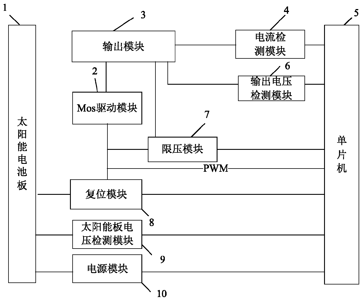
[0096] Such as figure 1 The solar charger control circuit shown includes a Mos drive module 2, an output module 3, a current detection module 4, a single chip microcomputer 5, an output voltage detection module 6, a voltage limiting module 7, a reset module 8, a solar panel voltage detection module 9 and a power supply Module 10; the connection relationship of the above modules is as follows:

[0097] The Mos drive module 2 is electrically connected to the output module 3, the voltage limiting module 7 and the reset module 8 respectively; the output module 3 is electrically connected to the current detection module 4, the output voltage detection module 6 and the voltage limiting module 7; The current detection module 4 , the output voltage detection module 6 , the voltage limiting module 7 , the reset module 8 , the solar panel voltage detection module 9 and the power sup...


PUM


Abstract

The invention discloses a solar charger control circuit and a solar charger. The solar charger control circuit comprises a MOS driving module, an output module, a current detecting module, a single-chip microcomputer, an output voltage detecting module, a voltage limiting module, a reset module, a solar panel voltage detecting module and a power module. The MOS drive module is electrically connected to the output module, the voltage limiting module and the reset module. The output module is electrically connected to the current detecting module, the output voltage detecting module and the voltage limiting module. The current detecting module, the output voltage detecting module, the voltage limiting module, the reset module, the solar panel voltage detecting module and the power module areelectrically connected to the single-chip microcomputer. The invention can improve the utilization rate of solar energy.

Description

technical field [0001] The invention belongs to the technical field of chargers, and in particular relates to a solar charger control circuit and a solar charger. Background technique [0002] The existing charger is generally an intermediate conversion device, which converts AC power into DC power and stores it in the battery of mobile phones and other equipment. It has the advantages of convenient use and simple operation. But this kind of charger is only used as a transmission medium between the power supply and equipment such as mobile phones. When people go out or have no power supply indoors, people cannot charge equipment such as mobile phones in time. It is highly dependent on the power supply, and the charger cannot be used after disconnecting from the power supply, which affects the normal use of mobile phones and other equipment. [0003] In response to the above problems, people have invented a mobile charger, which can be fully charged when there is a power sup...

Claims


Application Information

Patent Timeline
Patent Type & Authority Applications(China)
IPC IPC(8): H02J7/00H02J7/35
CPCH02J7/35H02J7/00
Inventor 彭家丽
Owner 深圳市辉曜科技有限公司
Why Eureka
Try Eureka