
Optimal operation method for multi-energy complementary system

An operation method and system optimization technology, which is applied in the field of multi-energy complementary system optimization operation, can solve the problem of less consideration of equipment variable operating conditions, failure to provide sufficient margin for new energy access, and failure to fully reflect electricity, heat, and gas. System correlation and other issues to achieve the effect of high energy utilization efficiency

Pending Publication Date: 2019-08-16
SHANGHAI UNIVERSITY OF ELECTRIC POWER
View PDF2 Cites 11 Cited by
  • Summary
  • Abstract
  • Description
  • Claims
  • Application Information

AI Technical Summary

Problems solved by technology

[0004] At present, there are two main problems in the research on the optimal operation of multi-energy complementary systems: 1. The constructed coupling system is not perfect, and does not fully reflect the correlation between the electricity, heat and gas systems, and the input and output are simple linear coupling relationships , seldom consider the changing operating conditions of the equipment, and fail to provide sufficient margin for the subsequent access of a large number of new energy sources; 2. The optimized operation result is a static curve, which fails to fully consider the impact of new energy fluctuations and load forecast errors on the system influence, unable to reflect the dynamic response of the multi-energy complementary system to its fluctuation degree

Method used


Image

  • Optimal operation method for multi-energy complementary system
  • Optimal operation method for multi-energy complementary system
  • Optimal operation method for multi-energy complementary system

Examples


Embodiment Construction

[0099] The present invention will be described in detail below in conjunction with the accompanying drawings and specific embodiments.

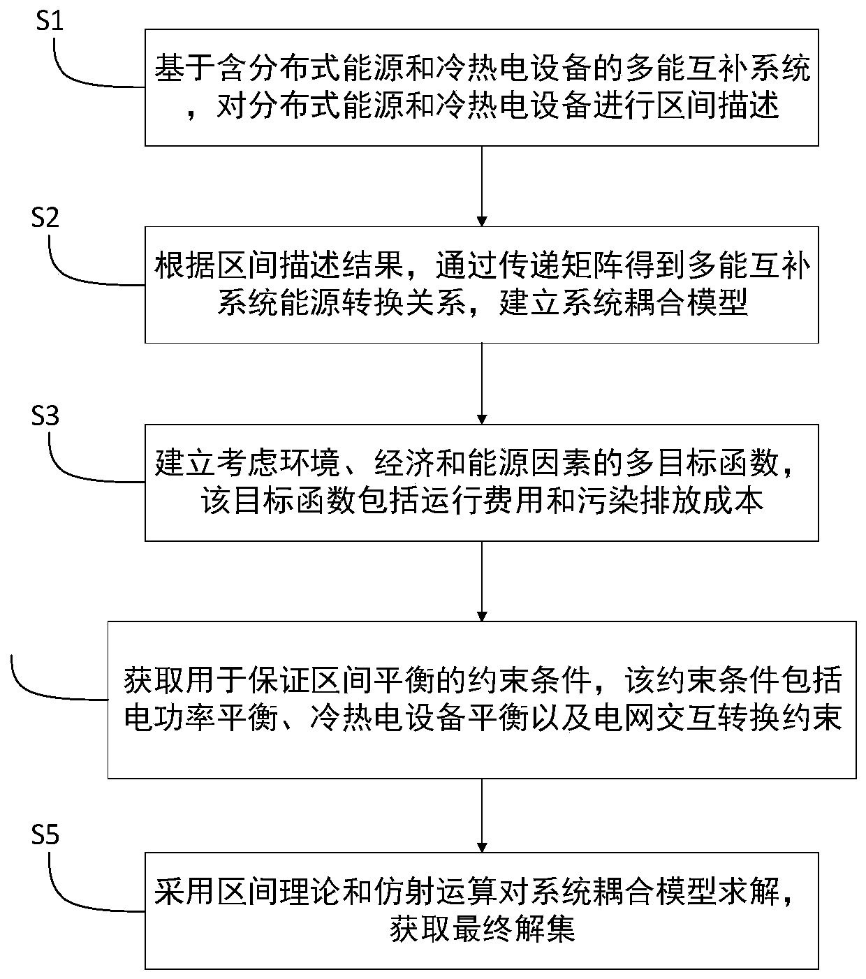
[0100] Such as figure 1 As shown, a multi-energy complementary system optimization operation method includes the following steps:

[0101] S1. Based on the multi-energy complementary system including distributed energy and cooling and heating equipment, the interval description of distributed energy and cooling and heating equipment is carried out;

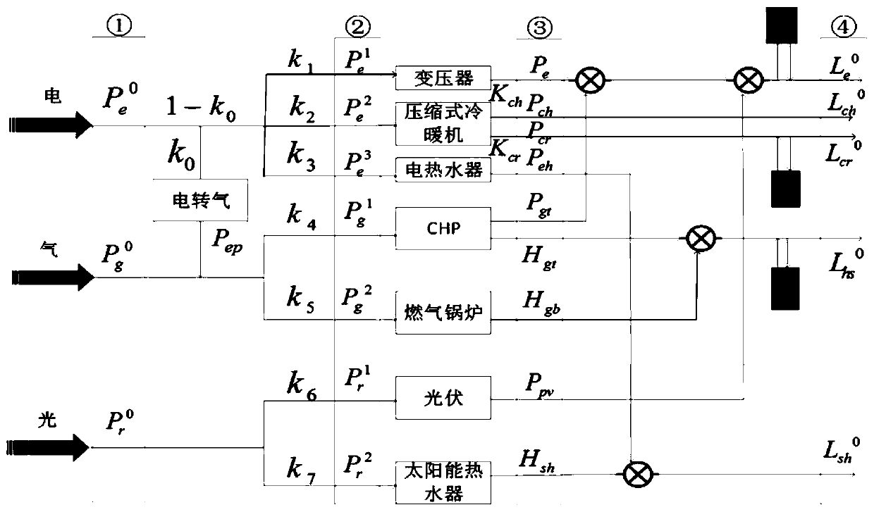
[0102] S2. According to the interval description results, the energy conversion relationship of the multi-energy complementary system is obtained through the transfer matrix, and the system coupling model is established;

[0103] S3. Establishing a multi-objective function that considers environmental, economic and energy factors, the objective function includes operating costs and pollution discharge costs;

[0104] S4. Acquiring constraint conditions for ensuring interval balance, the constra...


PUM


Abstract

The invention relates to an optimal operation method for a multi-energy complementary system, which includes the following steps: S1, carrying out interval description on distributed energy and cooling-heating-power equipment based on the structure of a multi-energy complementary system; S2, establishing a system coupling model according to the interval description result; S3, establishing a multi-objective function considering environmental, economic and energy factors, wherein the multi-objective function includes the operation cost and the pollution emission cost; S4, acquiring constraintsused to ensure interval balance, wherein the constraints include electric power balance, cooling-heating-power equipment balance and grid interaction conversion constraints; and S5, solving the systemcoupling model based on the interval theory and affine operation to obtain a final solution set. Compared with the prior art, coupling modeling is carried out on the energy devices of the system, andthe model is solved based on the interval theory and affine operation, which can reduce the dynamic impact of prediction error and energy fluctuation on the system, realize optimal allocation of resources and improve the energy utilization efficiency of the multi-energy complementary system.

Description

technical field [0001] The invention relates to the technical field of power systems, in particular to an optimal operation method for a multi-energy complementary system. Background technique [0002] With the gradual depletion of fossil energy and the increasingly serious environmental pollution, how to realize the clean and efficient operation of the power system has gradually become the focus of research by experts and scholars. The multi-energy complementary system couples the four energy sources of cold, heat, electricity, and gas, integrates the advantages of various energy sources, and establishes an integrated energy supply system to provide users with various load demands such as cooling, heat, and electricity, and realize the integration of various energy sources. The complementary utilization among them has the advantages of reducing system operating costs, improving energy utilization efficiency, and reducing pollution emissions. [0003] However, the coupling ...

Claims


Application Information

Patent Timeline
IPC IPC(8): H02J3/38H02J3/28G06Q10/04G06Q50/06
CPCH02J3/381H02J3/28G06Q10/04G06Q50/06H02J3/003H02J2203/20Y04S10/50Y02E40/70
Inventor 包伟涔韦钢高倩
Owner SHANGHAI UNIVERSITY OF ELECTRIC POWER
Learn More