
temperature detection circuit

A temperature detection circuit and branch circuit technology, applied in the circuit field, can solve the problems of exceeding the detection range of the ADC module and the small detectable temperature range of the temperature detection circuit, and achieve the effect of expanding the temperature detection range and high temperature detection accuracy

Active Publication Date: 2021-10-26
SPREADTRUM COMM (SHANGHAI) CO LTD
View PDF5 Cites 0 Cited by
  • Summary
  • Abstract
  • Description
  • Claims
  • Application Information

AI Technical Summary

Problems solved by technology

[0004] Since the power supply and the pull-up resistor are fixed, when the temperature range is large, the resistance value of the thermistor is in a very wide range, which leads to a wide range of voltage values ​​on the NTC thermistor. It may exceed the detection range of the ADC module, so the detectable temperature range of the existing temperature detection circuit is small

Method used


Image

  • temperature detection circuit
  • temperature detection circuit
  • temperature detection circuit

Examples


Embodiment Construction

[0026] In order to make the purpose, technical solutions and advantages of the embodiments of the present invention clearer, the technical solutions in the embodiments of the present invention will be clearly and completely described below in conjunction with the drawings in the embodiments of the present invention. Obviously, the described embodiments It is only some embodiments of the present invention, but not all embodiments. Based on the embodiments of the present invention, all other embodiments obtained by persons of ordinary skill in the art without making creative efforts belong to the protection scope of the present invention.

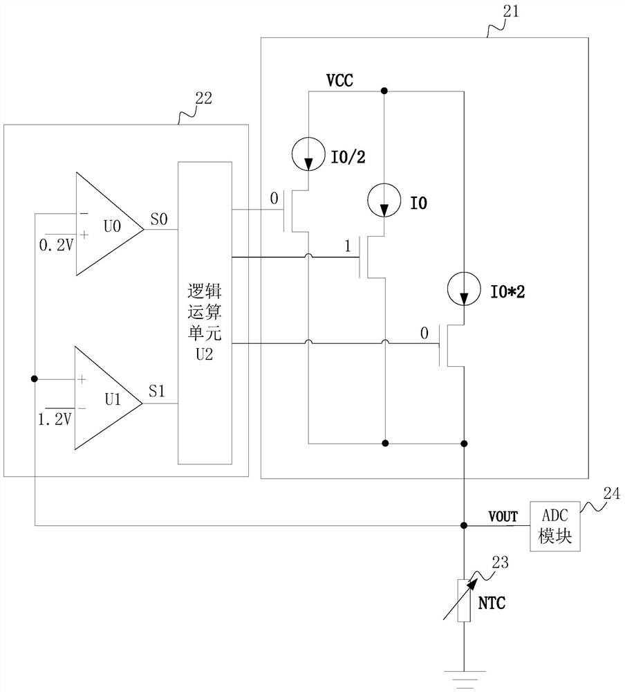
[0027] An embodiment of the present invention provides a temperature detection circuit, such as figure 2 As shown, it includes: a controllable current source module 21, a current source adjustment module 22, a thermistor 23 and an ADC module 24, wherein,

[0028] The controllable current source module 21 has multiple current gears, is contr...


PUM


Abstract

The invention provides a temperature detection circuit, including: a controllable current source module, a current source adjustment module, a thermistor and an ADC module, wherein the controllable current source module has multiple current gears, and the control of the current source adjustment module Output the current of one of the gears, and the current generates a detection voltage signal on the thermistor; the current source adjustment module is used to output the control signal according to the detection voltage signal to control the controllable current source module to output multiple current gears The current of one of the stalls makes the detection voltage signal meet the input range of the ADC module; the ADC module is used to deduce the temperature according to the detection voltage signal when the detection voltage signal meets the input range. The invention can expand the temperature detection range.

Description

technical field [0001] The invention relates to the technical field of circuits, in particular to a temperature detection circuit. Background technique [0002] In order to ensure the safety of mobile devices, smart terminal devices or batteries, etc., the temperature of these devices will be detected. At present, the most widely used is realized through the resistance voltage division scheme. The specific temperature detection circuit is as follows: figure 1 As shown, the pull-up resistor R1 and the NTC (negative temperature coefficient) thermistor are connected in series between the power supply VCC and the ground, and the ADC module can invert the current temperature according to the voltage VOUT on the NTC thermistor, thereby realizing the temperature detection. [0003] In the process of realizing the present invention, the inventor found that there are at least the following technical problems in the prior art: [0004] Since the power supply and the pull-up resisto...

Claims


Application Information

Patent Timeline
Patent Type & Authority Patents(China)
IPC IPC(8): G01K7/22
CPCG01K7/22
Inventor 雷鹏香妹董泰安
Owner SPREADTRUM COMM (SHANGHAI) CO LTD
Learn More