
Universal caster and connecting structure and adjusting method of universal caster and connecting structure

A technology of universal casters and connection structures, which is applied in the direction of casters, wheels, transportation and packaging, etc. It can solve problems affecting the life of universal casters, wear of brake pads, and deterioration of brake stability, so as to avoid equipment hitting the wall and improve The effect of service life and convenient turning

Inactive Publication Date: 2019-08-13
中山市唯信脚轮制造有限公司
View PDF6 Cites 2 Cited by
  • Summary
  • Abstract
  • Description
  • Claims
  • Application Information

AI Technical Summary

Problems solved by technology

[0004] 1. Although the description states that "the so-called brakeable caster with a brake assembly means that the caster can be braked by activating the brake assembly or rolled by releasing the brake assembly", so it does not disclose the application of this structure The brake assembly of the swivel caster, while the brake assembly on the traditional swivel caster is generally installed on the roller, which will move with the rotation of the roller, for example, the application number is 201410227971. Chinese invention patent, so it is impossible to use the transmission shaft to connect the brake components of multiple traditional swivel casters;
[0005] 2. For medical equipment such as hospital beds, it is often necessary to switch the universal casters between directional movement and universal movement, but the universal casters of this structure cannot move directional;
[0006] 3. The traditional pedal drives the brake pads to brake, which is easy to wear the brake pads, which in turn leads to poor braking stability and affects the life of the universal caster

Method used


Image

  • Universal caster and connecting structure and adjusting method of universal caster and connecting structure
  • Universal caster and connecting structure and adjusting method of universal caster and connecting structure
  • Universal caster and connecting structure and adjusting method of universal caster and connecting structure

Examples


Embodiment Construction

[0049] The following are specific embodiments of the present invention and in conjunction with the accompanying drawings, the technical solutions of the present invention are further described, but the present invention is not limited to these embodiments.

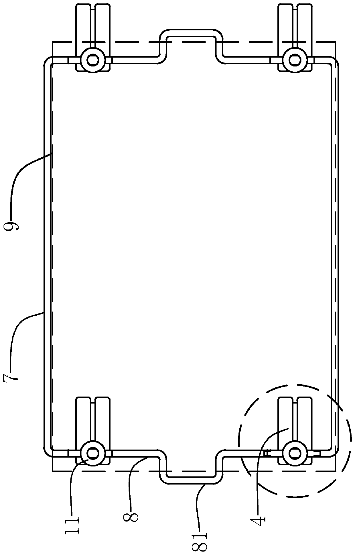
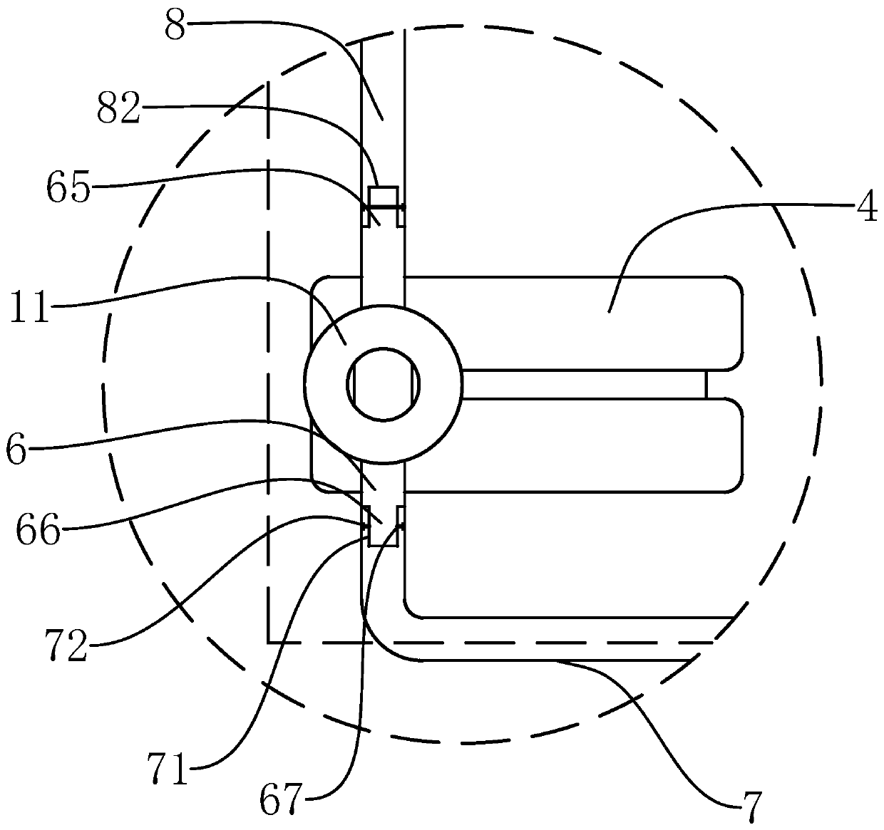
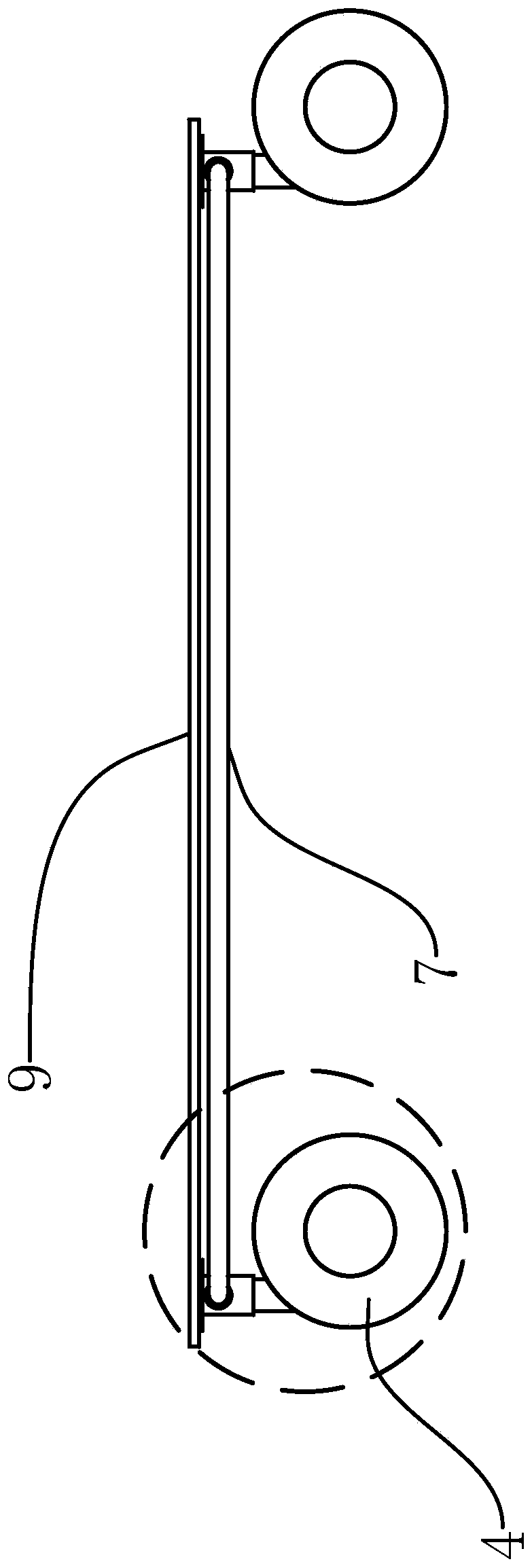
[0050] Such as Figure 1-8 As shown, a universal caster and connection structure of the present invention includes a universal caster, and the universal caster includes a round sleeve-shaped steering sleeve 2 with a fixed sleeve 1 that is movable at the top, and a fixed plate 11 is fixed on the top of the fixed sleeve 1. The outer wall of the sleeve 2 is coaxially provided with a circle of annular chute 21, the inner wall of the fixed sleeve 1 is provided with a slider 12 that slides on the chute 21, and the steering sleeve 2 can rotate around the axis of the fixed sleeve 1, and is also fixed on the bottom of the steering sleeve 2. The ring-shaped wheel frame 3 at the end of the wheel frame 3 is a hollow structure inside, ...


PUM


Abstract

The invention provides a universal caster and connecting structure and an adjusting method of the universal caster and connecting structure, and belongs to the field of universal casters. According tothe universal caster and connecting structure and the adjusting method of the universal caster and connecting structure, the problems that existing universal casters cannot brake synchronously and cannot move directionally are solved. The universal caster and connecting structure includes four universal casters and an adjusting frame connected with the four universal casters. Each universal caster includes a turning sleeve, a wheel frame, two rollers, a brake pipe, an adjusting rod and an adjusting column, wherein a fixing sleeve sleeves the top end of the turning sleeve, the wheel frame is fixed to the bottom end of the turning sleeve, the wheel frame includes an inner ring and an outer ring, the two rollers are connected with the wheel rings, the inner ring movably sleeve the wheel rings, the brake pipe is located in the wheel frame, a brake column is arranged in the brake pipe, an adjusting block is fixed to the adjusting rod, an alignment ring is fixed to the inner wall of the fixing sleeve, an adjusting hole is formed in the inner wall of the fixing sleeve, the adjusting column is arranged in the adjusting hole in a perforating mode, and an adjusting groove is formed in the column wall of the adjusting column. According to the universal caster and connecting structure and the adjusting method of the universal caster and connecting structure, the four universal casters areconnected by the adjusting frame, so that the universal casters can be switched among universal movement, directional movement and braking casters synchronously and quickly.

Description

technical field [0001] The invention belongs to the technical field of universal casters, and relates to a universal caster, a connection structure and an adjustment method thereof. Background technique [0002] The bottom of the movable medical equipment will have universal casters. The braking device of the existing universal casters usually adopts brake pads to brake. The brake pads are driven by stepping on the pedal to brake the universal casters. The swivel casters are all independent braking structures, resulting in the need to operate the brakes one by one, and the braking stability is poor. [0003] The existing application number is 201310237343.5, a Chinese invention patent named "caster device", which connects the brake assembly with the brake assembly of the first caster and the second caster, so that the first caster can be controlled by depressing or lifting the main pedal. The combined braking or release of the caster and the second caster, so that the brake...

Claims


Application Information

Patent Timeline
Patent Type & Authority Applications(China)
IPC IPC(8): B60B33/00B60B33/02
CPCB60B33/0002B60B33/0028B60B33/02B60B2200/26
Inventor 黄士玉
Owner 中山市唯信脚轮制造有限公司
Learn More