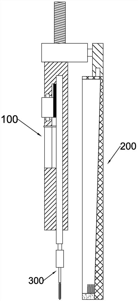
bloodletting tools
A tool and blood stasis technology, applied in the field of blood stasis and bloodletting tools, can solve the problems of wasting medical resources, damaging incision tissue, and increasing the chance of contamination, and achieve the effects of cost reduction and convenient control of the expansion and contraction length
- Summary
- Abstract
- Description
- Claims
- Application Information
AI Technical Summary
Problems solved by technology
Method used
Image
Examples
Embodiment 1
[0043] refer to Figures 1 to 7The blood stasis and bloodletting tool proposed in the first embodiment includes a handle part 100, a disposable bloodletting head 300 and a disposable blood storage tool 200, the handle part 100 includes a handle 12, and a telescopic rod 13 is slidably installed in the handle 12, The end of the telescopic rod 13 is equipped with a disposable bloodletting head 300 for discharging blood stasis. The handle 12 is provided with a runner 21, and the telescopic rod 13 is provided with a tooth 20 meshing with the runner 21. The runner 21 passes through the tooth 20. The meshing drives the telescopic rod 13 to move. The disposable phlebotomy head 300 includes a connector 4 and a bloodletting plate 1 for frictional wound bleeding. The connector 4 is provided with a communication hole 5 and a metal sheet 6. The end of the telescopic rod 13 is provided with a The magnet 10 adsorbed to the metal sheet 6, the other end of the handle 12 is provided with a firs...
Embodiment 2
[0049] This embodiment optimizes the function of the disposable blood storage tool 200 on the basis of the first embodiment. Specifically: refer to Figure 7 , the disposable blood storage tool 200 also includes a connecting block 30, the connecting block 30 can be screwed with the first threaded head 14, the fixed block 33 and the connecting block 30 are connected by a rotating rod 32, and the rotating rod 32 can be connected to the connecting block 30 Turn, the connecting block 30 has a threaded hole 31 that runs through the connecting block 30, and the threaded hole 31 is threadedly engaged with the first threaded head 14. Rotating rod 32 is divided into two parts, and a part is the cylinder that is connected with fixed block 33, and another part is the sphere on the cylinder, and spheroid is positioned at connecting block 30, and the spheroid of rotating rod 32 can rotate relative to connecting block 30 and can't move out of connecting. Block 30, when the handle 12 is use...
Embodiment 3
[0054] In this embodiment, the function of the handle part 100 is optimized, which facilitates the control of the depth of the telescopic rod 13 extending into the wound. Specifically, refer to figure 2 with 3 , telescopic rod 13 is provided with measuring rod 17, and handle 12 end faces are provided with second scale 22, and handle 12 is provided with the slide bar groove 15 that communicates with movable groove 16, and measuring rod 17 slides in slide bar groove 15. The shape of the measuring rod 17 is L-shaped, wherein the vertical part of the measuring rod 17 is connected with the telescopic rod 13 and slides in the slide rod groove 15, and the horizontal part of the measuring rod 17 is located at the outside of the handle 12 and slides with the end surface of the handle 12 Cooperate and the horizontal part is located above the second scale 22 at the same time, the measuring rod 17 can move along with the movement of the telescopic rod 13, while moving, the horizontal pa...
PUM
 Abstract
Description
Claims
Application Information
 - R&D Engineer
- R&D Manager
- IP Professional
- Industry Leading Data Capabilities
- Powerful AI technology
- Patent DNA Extraction
Browse by: Latest US Patents, China's latest patents, Technical Efficacy Thesaurus, Application Domain, Technology Topic, Popular Technical Reports.
© 2024 PatSnap. All rights reserved.Legal|Privacy policy|Modern Slavery Act Transparency Statement|Sitemap|About US| Contact US: help@patsnap.com


