
Data transmission method and device

A data transmission method and data technology, applied in the field of data transmission, can solve problems such as unreasonable bandwidth occupation and poor image effect at the receiving end, and achieve the effect of solving unreasonable bandwidth occupation and reducing bandwidth occupation

Active Publication Date: 2021-04-20
上海京像微电子有限公司
View PDF9 Cites 0 Cited by
  • Summary
  • Abstract
  • Description
  • Claims
  • Application Information

AI Technical Summary

Problems solved by technology

[0004] The embodiments of the present disclosure provide a data transmission method and device, which can solve the problems of unreasonable bandwidth occupation and poor image quality at the receiving end in existing technical solutions

Method used


Image

  • Data transmission method and device
  • Data transmission method and device
  • Data transmission method and device

Examples


Embodiment Construction

[0056] Reference will now be made in detail to the exemplary embodiments, examples of which are illustrated in the accompanying drawings. When the following description refers to the accompanying drawings, the same numerals in different drawings refer to the same or similar elements unless otherwise indicated. The implementations described in the following exemplary examples do not represent all implementations consistent with the present disclosure. Rather, they are merely examples of apparatuses and methods consistent with aspects of the present disclosure as recited in the appended claims.

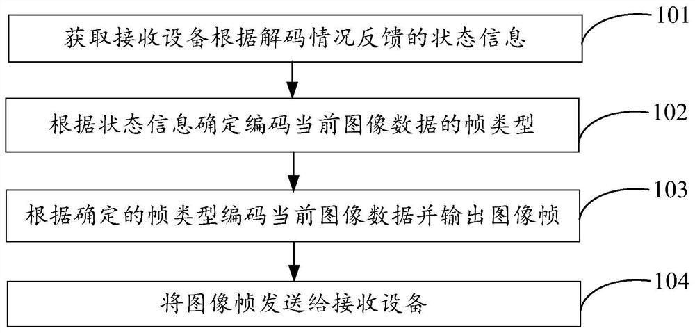
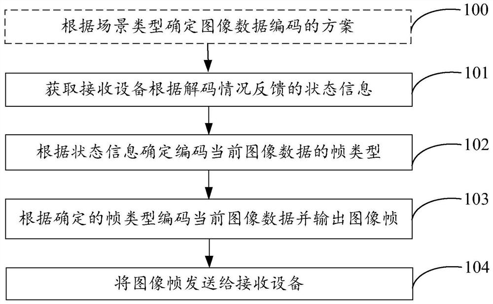
[0057] An embodiment of the present disclosure provides a data transmission method, which is applied to an encoder, such as figure 2 As shown, the method includes the following steps:

[0058] 101. Acquire state information fed back by a receiving device according to a decoding situation.

[0059] Wherein, the state information includes: reference frame decoding success, reference f...


PUM


Abstract

The data transmission method and device provided in the present disclosure relate to the technical field of data transmission, and can solve the problems of unreasonable bandwidth occupation and poor image effect at the receiving end existing in the prior art solutions. The specific technical solution is: first obtain the state information fed back by the receiving device according to the decoding situation, wherein the state information includes: reference frame decoding success, reference frame decoding failure, or reference frame loss, and then determine the frame type for encoding the current image data according to the state information , and then encode the current image data according to the determined frame type and output the image frame, and finally send the image frame to the receiving device. The disclosure is used to optimize the bandwidth occupation of image transmission and improve the image effect at the receiving end.

Description

technical field [0001] The present disclosure relates to the technical field of data transmission, and in particular, to a data transmission method and device. Background technique [0002] The common frame types in video codec are divided into: I frame (Intra-coded picture, intra-frame coded frame), P frame (Predictive-coded picture, forward predictive coded frame), and B frame (Bidirectionally predicted picture, bidirectionally predicted intra Insert coded frame), the reference relationship in GOP (Group Of Pictures, frame sequence) is as follows figure 1 As shown, among them, the I frame is an independent frame with all the information, and can be decoded independently without referring to other images; the P frame needs to be encoded by referring to the previous I frame or P frame; the B frame generally needs to refer to the previous I frame Frame or P frame and the following I frame or P frame encoding. Among them, the GOP length is set to a fixed length when the enco...

Claims


Application Information

Patent Timeline
Patent Type & Authority Patents(China)
IPC IPC(8): H04N19/172H04N19/177H04N19/44
CPCH04N19/172H04N19/177H04N19/44
Inventor 范志刚周毅
Owner 上海京像微电子有限公司
Learn More