Camera automatic rotation control method and system of smart device
An intelligent device and automatic rotation technology, which is applied in the parts of TV systems, image communication, color TV parts, etc. , to avoid vulnerable effects
- Summary
- Abstract
- Description
- Claims
- Application Information
AI Technical Summary
Problems solved by technology
Method used
Image
Examples
Embodiment 1
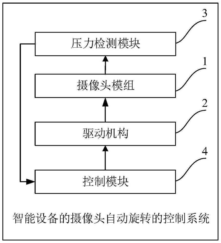
[0056] Such as figure 2 As shown, the camera automatic rotation control system of the smart device in this embodiment includes a camera module 1 , a driving mechanism 2 , a pressure detection module 3 and a control module 4 .
[0057] Wherein, the driving mechanism 2 includes but not limited to a motor, and the pressure detection module 3 includes but not limited to a pressure sensor.
[0058] The driving mechanism 2 is connected with the camera module 1;
[0059] The pressure detection module 3 is electrically connected to the control module 4;
[0060]The pressure detection module 3 is arranged on the camera module 1, and is used to obtain the pressure value acting on the pressure detection module 3;
[0061] The control module 4 is used to obtain the pressure value, and judge whether the pressure value is greater than the first set threshold, if greater, then control the driving mechanism 2 to drive the camera module 1 to start automatic rotation, thereby replacing the e...
Embodiment 2
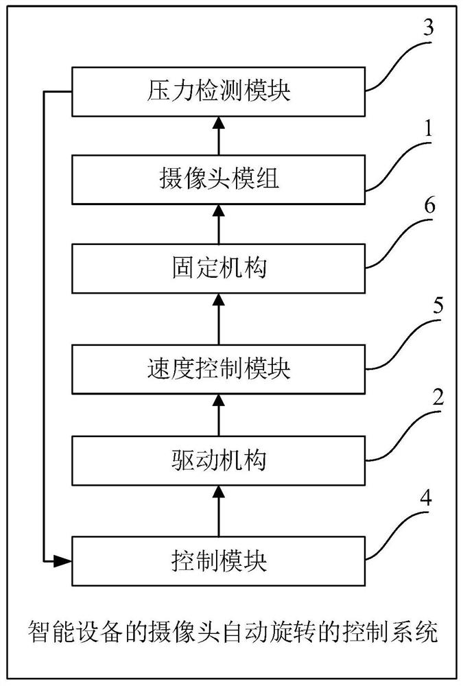
[0064] Such as image 3 As shown, the camera automatic rotation control system of the smart device in this embodiment is a further improvement on Embodiment 1, specifically:
[0065] A pressure detection module 3 is respectively provided on both sides of the camera module 1 perpendicular to the direction of rotation;
[0066] The control module 4 is used to obtain the pressure values obtained by the two pressure detection modules 3 , and when the pressure value detected by any pressure detection module 3 is greater than the first set threshold, control the driving mechanism 2 to drive the camera module 1 to start rotating.
[0067] When the camera module 1 is subjected to an external force in the direction of rotation during the rotation, the control module 4 is used to obtain the electrical signal in the drive mechanism 2, and judge whether the drive mechanism 2 is overloaded according to the electrical signal. The mechanism 2 controls the camera module 1 to stop rotating ...
Embodiment 3
[0090] The method for controlling the automatic rotation of the camera of the smart device in this embodiment is implemented by using the control system for the automatic rotation of the camera of the smart device in Embodiment 1.
[0091] Such as Figure 7 As shown, the method for controlling the automatic rotation of the camera of the smart device in this embodiment includes:
[0092] S101. Obtain a pressure value acting on the pressure detection module by using the pressure detection module;
[0093] S102. Use the control module to acquire the pressure value, and judge whether the pressure value is greater than the first set threshold, and if so, control the driving mechanism to drive the camera module to start automatic rotation.
[0094] In this embodiment, by setting the pressure detection module on the rotatable camera module, when the pressure on the pressure detection module exceeds the set threshold, the control drive mechanism drives the camera module to start rota...
PUM
 Abstract
Description
Claims
Application Information
 - R&D
- Intellectual Property
- Life Sciences
- Materials
- Tech Scout
- Unparalleled Data Quality
- Higher Quality Content
- 60% Fewer Hallucinations
Browse by: Latest US Patents, China's latest patents, Technical Efficacy Thesaurus, Application Domain, Technology Topic, Popular Technical Reports.
© 2025 PatSnap. All rights reserved.Legal|Privacy policy|Modern Slavery Act Transparency Statement|Sitemap|About US| Contact US: help@patsnap.com


