Calculation method for filling power in tight gas reservoir

A calculation method and tight gas technology, applied in the field of oil and gas reservoir exploration, can solve problems such as low precision and no specificity, and achieve the effect of simple steps and batch processing.

Inactive Publication Date: 2019-08-09
NORTHWEST UNIV
View PDF6 Cites 0 Cited by
  • Summary
  • Abstract
  • Description
  • Claims
  • Application Information

AI Technical Summary

Problems solved by technology

[0014] To sum up, among the current methods for studying gas reservoir charging dynamics, the effective inclusion method and immature source rock hydrocarbon generation simulation method both have the above-mentioned problems. The data is easy to obtain, the method is simple and easy to implement, but the accuracy is not high, and the minimum error is also ±2MPa
In "Calculation Method of Upper Paleozoic Charging Dynamics in Sulige Gas Field" (Chen Zhanjun et al., 2016), although new measures are used to improve the calculation accuracy, some steps are subjective, such as selecting layers with high shale content, shale How high is the content? How thick should the layer with high mud content be? How to draw up the trend line of normal compaction section? Is there a unified expression formula? The charging power in the reservoir can be characterized by the intermediate value of the overlying and underlying mudstone. How should the intermediate value be chosen? How to distinguish the normal compacted section from the under-compacted section has no specific operability content, so the corresponding calculation method is transformed into an executable, quantifiable, and unified calculation technology to achieve large-scale application. It is necessary to abandon the subjectivity, arbitrariness and flexibility of calculating a small number of wells

Method used


Image

  • Calculation method for filling power in tight gas reservoir
  • Calculation method for filling power in tight gas reservoir
  • Calculation method for filling power in tight gas reservoir

Examples


Embodiment

[0072] Embodiment: The example well is Zhao 25 ​​Well in East District of Sulige (hereinafter referred to as Z-EW well).

[0073] A charging dynamic calculation method for tight gas reservoirs, comprising the following steps:

[0074] 1. Read single well mudstone compaction data

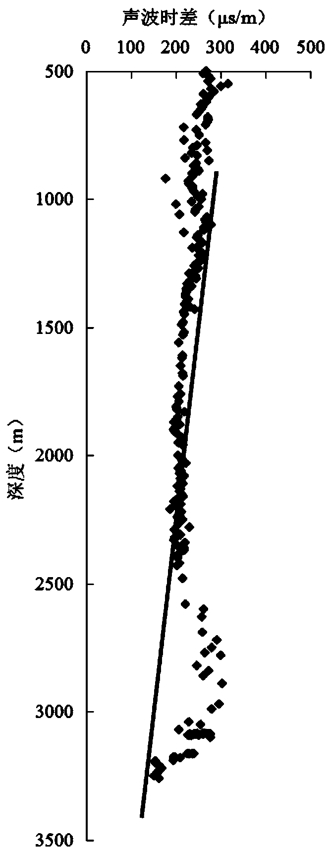
[0075] Starting from the initial depth, the acoustic time difference (AC for short) values ​​at different depths are read on the logging curve at intervals of corresponding depth steps.

[0076] According to technical requirements, the depth of Z-EW well is 3260m, so the AC value step is 10m. From the initial depth of 500m to the bottom of the well, a total of 277 AC data can be read.

[0077] 2. Fitting the depth-AC relationship of the non-hydrocarbon generation-normal compaction section

[0078] (1) Establish a depth-AC intersection relationship diagram;

[0079] The above 277 AC values ​​and corresponding depths are used to establish a depth-AC intersection relationship diagram, such as figur...


PUM


Abstract

The invention discloses a calculation method for filling power in a tight gas reservoir. The calculation method includes the following steps that (1) data of the compaction degree of single well mudstone is read on a logging curve; (2) a depth-AC relationship of a non-hydrocarbon generation-normal compaction section is fit to obtain an expression of a trend line of the normal compaction section; (3) data screening of a hydrocarbon generation-undercompaction section is performed, firstly the depth and corresponding muddy content in the logging curve are drawn into a depth-lithology longitudinalsection view and calculation data of the undercompaction section is selected in the section view; (4) overpressure of fluid is calculated, that is, the filling power is calculated, and calculation results are marked on a data screening section of the section view; and (5) the filling power provided by the marine source rock and the filling power obtained by the reservoir are represented. According to the calculation method for the filling power in the tight gas reservoir, screening of a mudstone section is added and standardized, the data between well points can compared, then through the fitting of the compaction trend and the filling power calculation, the size of the filling power is finally obtained, and the calculation process is more concise, more accurate and more comparable.

Description

technical field [0001] The invention belongs to the technical field of oil and gas reservoir exploration, and in particular relates to a calculation method for charging dynamics of tight gas reservoirs. Background technique [0002] The reason why oil and gas can migrate and charge is mainly due to certain differences between source rocks and reservoirs, such as fluid potential difference, density difference, concentration difference, etc. During the evolution of oil and gas-bearing formations in geological history, It is necessary to reduce and reconcile these differences, resulting in the accumulation and accumulation of generated oil and gas under different dynamic mechanisms. In terms of mechanism, the fluid potential difference can form directional flow to make oil and gas migrate and accumulate, while the density difference shows that oil and gas accumulate and accumulate due to the vertical differentiation of fluids due to different densities, and the concentration di...

Claims


Application Information

Patent Timeline
IPC IPC(8): E21B49/00
CPCE21B49/00
Inventor 任战利陈占军祁凯
Owner NORTHWEST UNIV
Why Eureka
Try Eureka